Oilfield lift cap and combination tools

a technology of oilfield lifts and combination tools, which is applied in the direction of drilling casings, drilling pipes, load-engaging elements, etc., can solve the problems of rig workers having the difficult task of not being able to make up tiws or kellys, rig workers have the potential to injure rig workers, etc., and achieve the effect of quick and easy disassembly

Active Publication Date: 2016-08-02
DWJ
View PDF52 Cites 6 Cited by
  • Summary
  • Abstract
  • Description
  • Claims
  • Application Information

AI Technical Summary

Benefits of technology

[0012]a one-piece, formed (defined herein as including milled, machined, molded, cast, machined or milled billet, but not welded or brazed), planar metallic upper section having a longitudinal axis, the upper section comprising a pair of longitudinal members defining a central open region, each longitudinal member having a lower end, the longitudinal members joined by a top manipulating end having one or more lifting features formed therein configured to accept one or more manipulators (cables, chains, straps, or ropes connected to a rig hoist), the one or more formed lifting features positioned such that when the modular tool body and a rig tool (such as an IBOP, TIW valve, drill stem test valve, kelly valve, and the like) connected thereto are lifted by the one or more manipulators, they are easily moved over, aligned with, and connected with a working drillpipe or other valve while minimizing possibility of slipping off the cables, chains, or straps; and
[0030]An important feature of the apparatus and methods disclosed herein is the modularity, that is, the lower and upper sections of the modular tool body (and fluid diversion cap if present) may quickly and easily be disassembled, and the same upper section joined and used with another lower section of same or different outside diameter, such as if one section cracks or otherwise becomes unusable. In certain embodiments the lower section may be changed to accommodate a different diameter working drillpipe or rig tool, although that may rarely occur. In certain embodiments, the method comprises changing the lower section of the modular tool body to match size (outside diameter) of another rig tool prior to attaching the modular tool to another, different sized rig tool.

Problems solved by technology

However, with conventional lift caps there is presently no way for rig workers to make up a TIW or kelly valve, an IBOP valve, or any other component with the drill string unless the workers use the drill rig air hoist to lift the component by the conventional cap and walk in a circle while making it up with the drill string, either with or with out use of chain tongs.
One of the above patents, U.S. Pat. No. 4,403,628, implies in Col. 3 of the patent that assembling an IBOP into a drill stem and removing the IBOP therefrom as just described, including lifting and manipulating the IBOP, is conveniently performed; however, this is contrary to experience, as accidents can and have occurred.
While the “iron” (slang term for rig tools) is accustomed to being dropped and otherwise abused on the rig, the rig workers have the difficult tasks of not only picking up the rig tools, using chains or straps with the air hoist or otherwise, but picking them up straight (vertical or substantially vertical) to align with and screw onto the working drillpipe, which more often than not has fluids and possibly solids escaping out at a high rate.
In the meantime, the valve or other rig components shift position and the conventional cap / valve combination slips off the chain, cable, or strap, with potential to injure rig workers, and without stopping flow from the drillpipe.
As may be seen, current practice of picking up, making up, and breaking out TIW valves, IBOPs, and other drill string components which must be picked up and made up to the drill string may not be adequate for all circumstances, and at worst have resulted in injury to rig workers.

Method used


Image

  • Oilfield lift cap and combination tools
  • Oilfield lift cap and combination tools
  • Oilfield lift cap and combination tools

Examples


embodiment 100

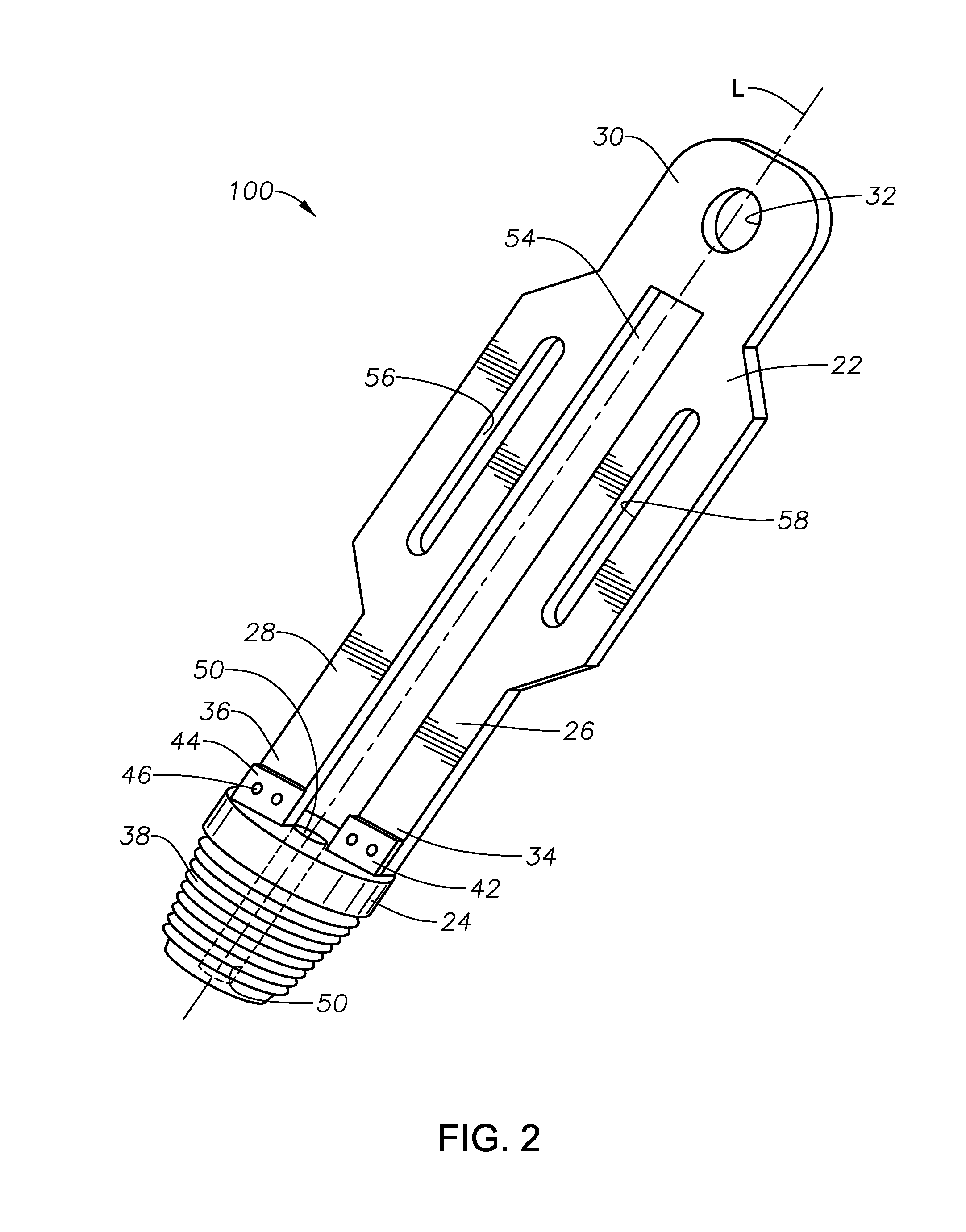
[0049]With these problems in mind, the modular tools of the present disclosure were developed. FIG. 2 is a schematic perspective view of one modular tool body embodiment 100 within the present disclosure. Modular tool body 100 includes an upper “flat iron” section 22 having a longitudinal axis “L”, and a lower tubular section 24 of same longitudinal axis. Upper section 22 is comprised of two longitudinal members 26, 28, joined by a top manipulating end 30. Upper section 22 is a one-piece, formed, planar, metallic component with no welds or components welded thereto. This eliminates the need for pull testing (tensile testing) in offshore applications. Longitudinal members 26, 28 define a central open region 54 there between, each longitudinal member having a lower end 34, 36, respectively. Top manipulating end 30 includes one or more lifting features 32 formed therein configured to accept one or more manipulator cables, chains, or straps (not illustrated), the one or more milled lift...

embodiment 350

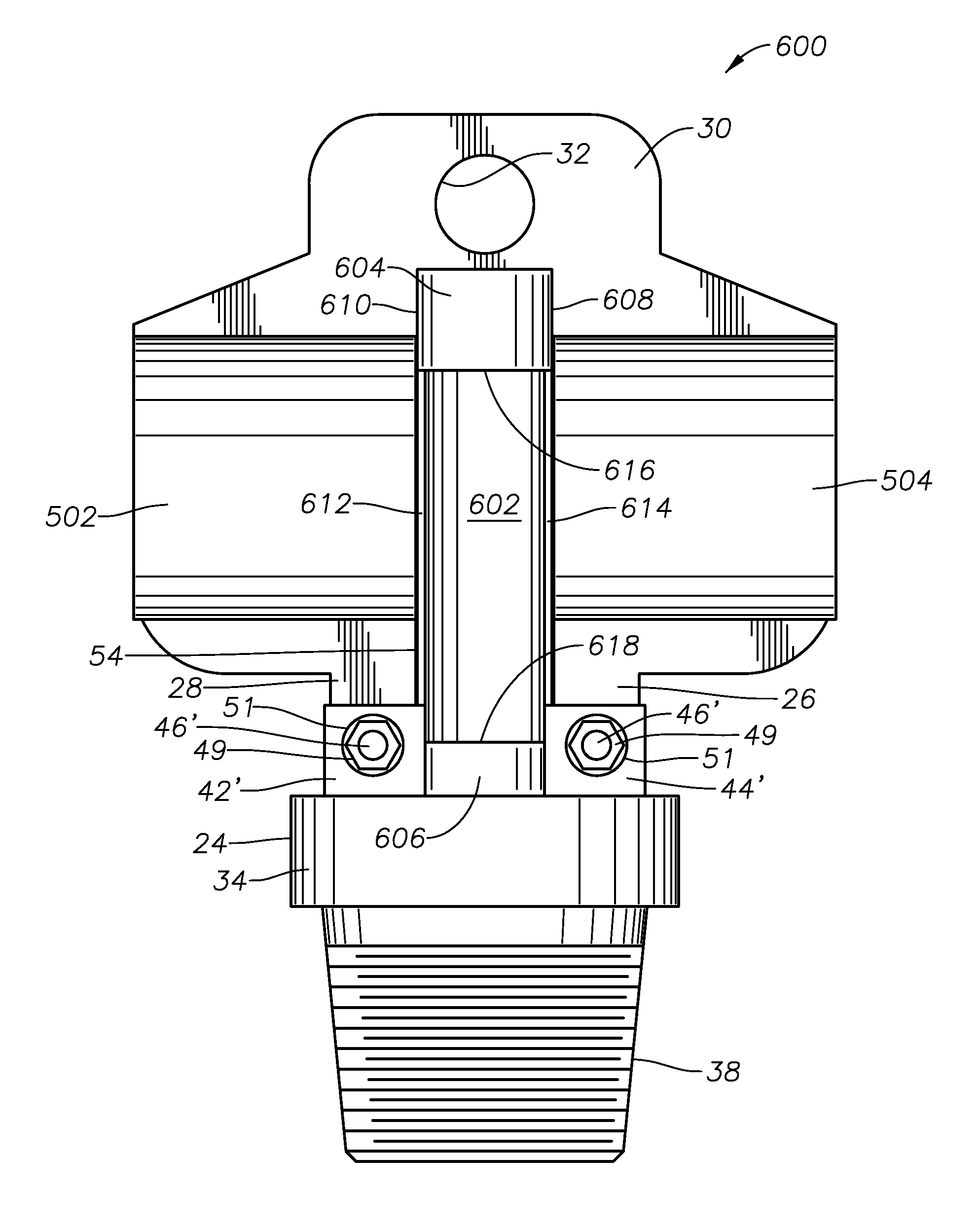
[0059]FIGS. 6 and 7 are schematic perspective views of another modular tool embodiment in accordance with the present disclosure, and side elevation views (partially in cross-section) of valves that may be picked up and stabbed using the modular tools of this disclosure. Embodiment 350 illustrated schematically in FIG. 6 actually is four embodiments of combinations of the modular tool formed by upper section 400 and lower section 24 combined with four different ball valves useful as kelly valves, safety valves, or top drive valves. For example, the kelly valve illustrated schematically at 320 is the kelly valve known under the trade designation ONE-PIECE CANISTER GUARD™ kelly valve; the kelly valve illustrated schematically at 330 is the kelly valve known under the trade designation TWO-PIECE CANISTER GUARD™ kelly valve; the safety valve illustrated schematically at 336 is the safety valve known under the trade designation TWO-PIECE CANISTER GUARD™ safety valve; and the valve illust...

embodiment 380

[0060]Embodiment 380 illustrated schematically in FIG. 7 actually is four embodiments of combinations of the modular tool formed by upper section 400 and lower section 24 combined with four different ball valves useful as kelly valves, safety valves, or top drive valves. For example, the top drive valve illustrated schematically at 340 is the top drive valve known under the trade designation TOP DRIVE BOTTOM LOAD™ SYSTEM, and the safety and kelly valve illustrated schematically at 345 is an old standard construction safety and kelly valve, both available from M & M International, Broussard, La., USA. The ball valve illustrated schematically at 355 in FIG. 7 is a schematic illustration of an API Class I ball type kelly valve, while the ball valve illustrated schematically at 360 in FIG. 7 is a schematic illustration of an API Class II ball type kelly valve, both available from TIW Corporation, Houston, Tex., USA. The construction and operation of these valves is well known and forms ...


PUM


Abstract

A modular tool body having upper and lower sections, a pair of longitudinal members define a central open region, the longitudinal members joined at one end having a lifting feature formed therein configured to accept a manipulator. The lifting feature is positioned such that when the modular tool body and a rig tool connected thereto are lifted by the manipulator, they are easily moved over, aligned with, and connected with a working drillpipe or other rig tool while minimizing possibility of the manipulator slipping off. The lower section includes a threaded end mating with a mating end of a rig tool, a central longitudinal bore, and an upper end formed to accept the lower ends of the longitudinal members of the upper section. Elongate slots in each longitudinal member define one or more manipulating handles. A pair of generally horizontal hand holds may be formed in each longitudinal member.

Description

BACKGROUND INFORMATION[0001]1. Technical Field[0002]The present disclosure relates to apparatus and methods in the onshore and marine (offshore) hydrocarbon exploration, production, drilling, well completion, well intervention, and leak containment fields. More particularly, the present disclosure relates to tools useful for pick up, make up, and / or break down operations for oilfield equipment having threaded connections, including, but not limited to, inside blowout preventers, TIW valves, drill stem safety valves, kelly valves, dart valves, flapper valves, ball valves, safety valves, top drive valves (upper and lower), and the like.[0003]2. Background Art[0004]There are many drill string / drill stem components that may require “picking up” (lifting) by drill rig workers and / or a drill rig draw works, air tugger, or air hoist. Presently, this is accomplished by attaching a conventional “lift cap” to the top of the component, and lifting the combination lift cap and component. The co...

Claims


Application Information

Patent Timeline
Patent Type & Authority Patents(United States)
IPC IPC(8): E21B19/02B66C1/66
CPCE21B19/02B66C1/66E21B17/042E21B19/002E21B19/16E21B33/06
Inventor WILLIAMS, DONALD L.
Owner DWJ
Why Eureka
Try Eureka