Pulsed light optical rangefinder
a technology of optical rangefinders and pulsed light, which is applied in the field of optical rangefinders, can solve the problems of complex system, complicated and costly optics for separating light, and the inability to expand the dynamic range of the whole monolith array, so as to reduce the photon detection rate of the receiver, increase the dynamic range, and prevent saturation
- Summary
- Abstract
- Description
- Claims
- Application Information
AI Technical Summary
Benefits of technology
Problems solved by technology
Method used
Image
Examples
second embodiment
FIG. 6, Second Embodiment, Alternative Configuration of Receiver, Using Shift Register,
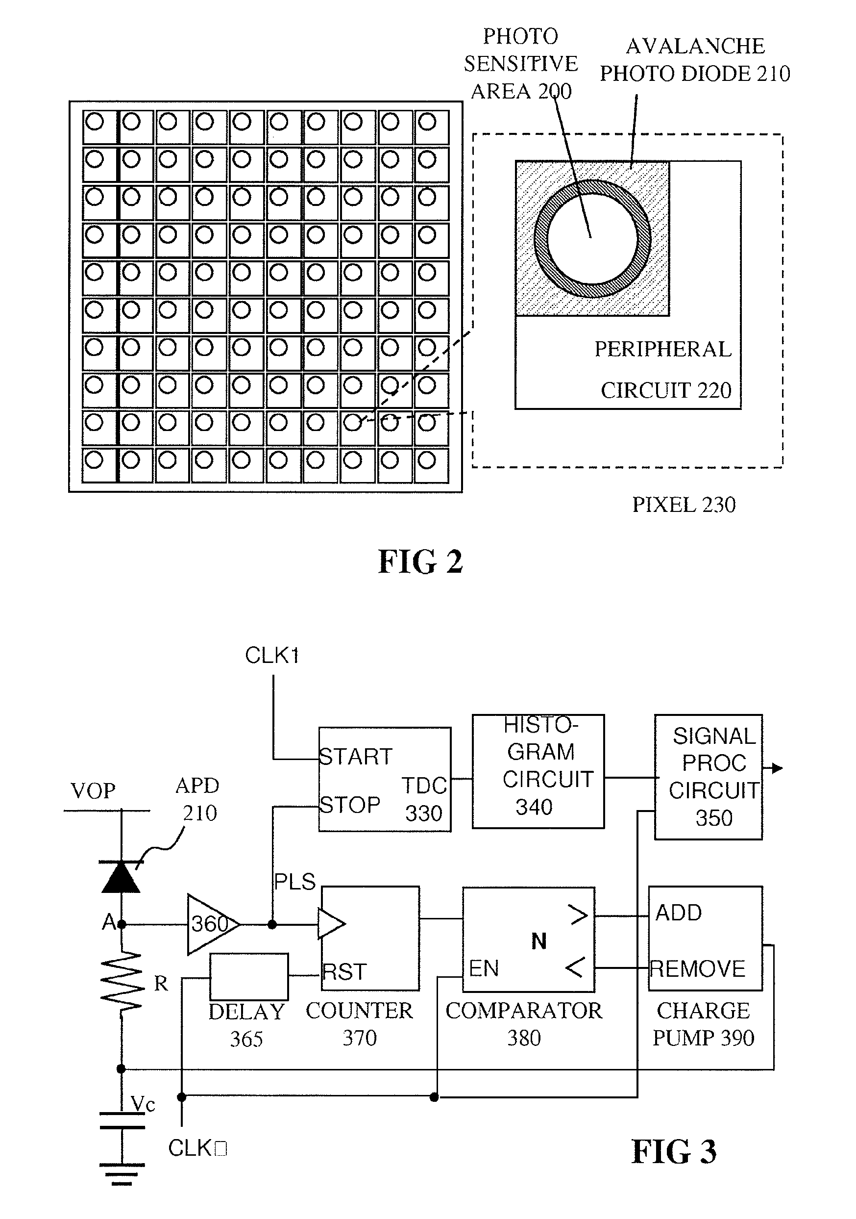
[0066]A second embodiment is shown in FIG. 6. The counter in FIG. 3 is replaced with an M-bit shift register 470 and an adder 475. The CLK1 is delayed for one pulse by delay element 365 and is input to the shift register. The shift register is updated with a period of T. When a pulse is input from the APD, upper 1 bit becomes 1, and when the shift register is updated, the lower 1 bit is discarded. The M bit shift register is always storing the M latest periods of information denoting existence of a pulse. At every pulse illumination, the adder counts a number of bits set at 1, and outputs it to the comparator. Operation of the comparator is the same as that in FIG. 3, but the period of EN is T instead of MT. Consequently, an update period of Vc is shortened by a factor of M and it is capable of adjusting more rapidly to follow sudden changes of incident light, and e.g. as well as noise level.
third embodiment
FIG. 7, Third Embodiment, Alternative Configuration Using Differential Counter
[0067]A third embodiment is shown in FIG. 7, in which the counter and comparator in FIG. 3 are replaced with a differential counter 570. The differential counter is incremented when a PLS from APD is input, and is decremented when a TRG is input. When EN is input, the sign of the counted number is output. If a photon detection cycle is longer than a TRG cycle, the accumulated count is positive, and Vc is lowered by the charge pump. Since the reverse bias voltage is increased, the photo detection probability is enhanced. If a photon detection cycle is shorter than a TRG cycle, the operation is reversed. Consequently, the reverse bias voltage can be controlled with the aim of equalizing the cycle of photon detection and TRG. The target cycle for photon detection can be easily set by changing the TRG cycle. Updating the cycle of Vc can also be done by changing a cycle of EN, and thus faster control of Vc is f...
PUM
 Abstract
Description
Claims
Application Information
 - R&D
- Intellectual Property
- Life Sciences
- Materials
- Tech Scout
- Unparalleled Data Quality
- Higher Quality Content
- 60% Fewer Hallucinations
Browse by: Latest US Patents, China's latest patents, Technical Efficacy Thesaurus, Application Domain, Technology Topic, Popular Technical Reports.
© 2025 PatSnap. All rights reserved.Legal|Privacy policy|Modern Slavery Act Transparency Statement|Sitemap|About US| Contact US: help@patsnap.com


