Arrow aiming apparatus for bowstring releases

a bowstring and aiming apparatus technology, applied in the field of arrow aiming invention, can solve the problems of complex target face, high variability, and significant challenge in aiming an arrow, and achieve the effect of improving shooting repeatability and improving aiming repeatability

Active Publication Date: 2016-08-30
LEDBETTER BELINDA JANE
View PDF13 Cites 14 Cited by
  • Summary
  • Abstract
  • Description
  • Claims
  • Application Information

AI Technical Summary

Benefits of technology

[0018]Pin sights and peep holes have evolved as the primary means to improve aiming repeatability of the shooter's anchor point and Line of Sight (LOS). Even though these devices improve the shooting repeatability they still include the complexity of parallax vision and may not compensate for arrow fall due to gravity when the bow is tilted out of the normally vertical setup plane.

Problems solved by technology

However, this position presents a significant challenge to aiming an arrow.
Determining the proper arrow pointing position for the trajectory to intersect the shooter's Line of Sight (LOS) at the desired point on the face of the target is complex with highly variable results.
This non-parallel aiming often described as parallax is counter intuitive and presents a negative impact on target acquisition, position repeatability and overall accuracy.
If the distance to the target is known, a problem may still arise when the sight pin system does not have a pin preset for the current shooting distance.
In this situation, the archer must shoot between the two pins closest to the current shooting distance thus sacrificing or losing additional accuracy.
Determining the proper correction and compensation for setting the location of the pins may be complex since it involves two independent variables, one for parallax and one for gravity compensation.
This additional adjustment or compensation for gravity further complicates intuitive aiming and setting of the pins.
Up or downhill shooting complicates the settings for these systems.
The sighting pins are typically positioned in the plane of the bowstring and arrow thus limiting their use to aiming with the bow in a vertical position or parallel to the force of gravity.
It also becomes more difficult for the shooter to see the pins through the peephole sight if the bow is tilted out of the setup plane.
Rotating the bow introduces significant aiming errors.
These limit and restrict a hunter's use of peep and pin sights because of the frequent need to position the bow out of the vertical plane to avoid tree limbs, bush and other obstacles.
Off axis peep sight aiming is also awkward and limited by the hunter's ability to see through the sights and estimate the distance to the target.
However, for less experienced shooters this non intuitive method of aiming often results in optical confusion and sighting inconsistencies since the shooter's Line of Sight (LOS) is not parallel to the arrow shaft.
As a further complication even experienced hunters sometimes complain that selecting the proper pin during a rushed aiming process can be disruptive and confusing often resulting in poor target acquisition.
However, this approach would require alteration of each arrow and add weight for the laser and power source to the arrow.
Their use may also be restricted by rules and regional regulations.
Viewing a low power laser spot at a distance in full daylight can be difficult at best.
However, conventional mounting of the laser to the bow again results in parallax aiming where the laser beam and the arrow path only cross at one point—U.S. Pat. No. 5,419,050.
Bright sunshine and / or dark targets absorb the laser light making it extremely difficult if not impossible to see the projected dots.
Because they are attached to the bow they too result in opportunities for parallax aiming errors.
Any inconsistencies between the arrow and the bow may contribute to poor target acquisition.

Method used


Image

  • Arrow aiming apparatus for bowstring releases
  • Arrow aiming apparatus for bowstring releases
  • Arrow aiming apparatus for bowstring releases

Examples


Embodiment Construction

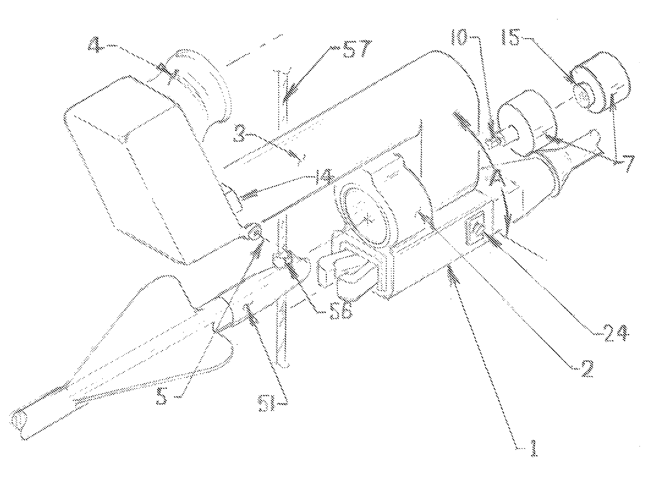
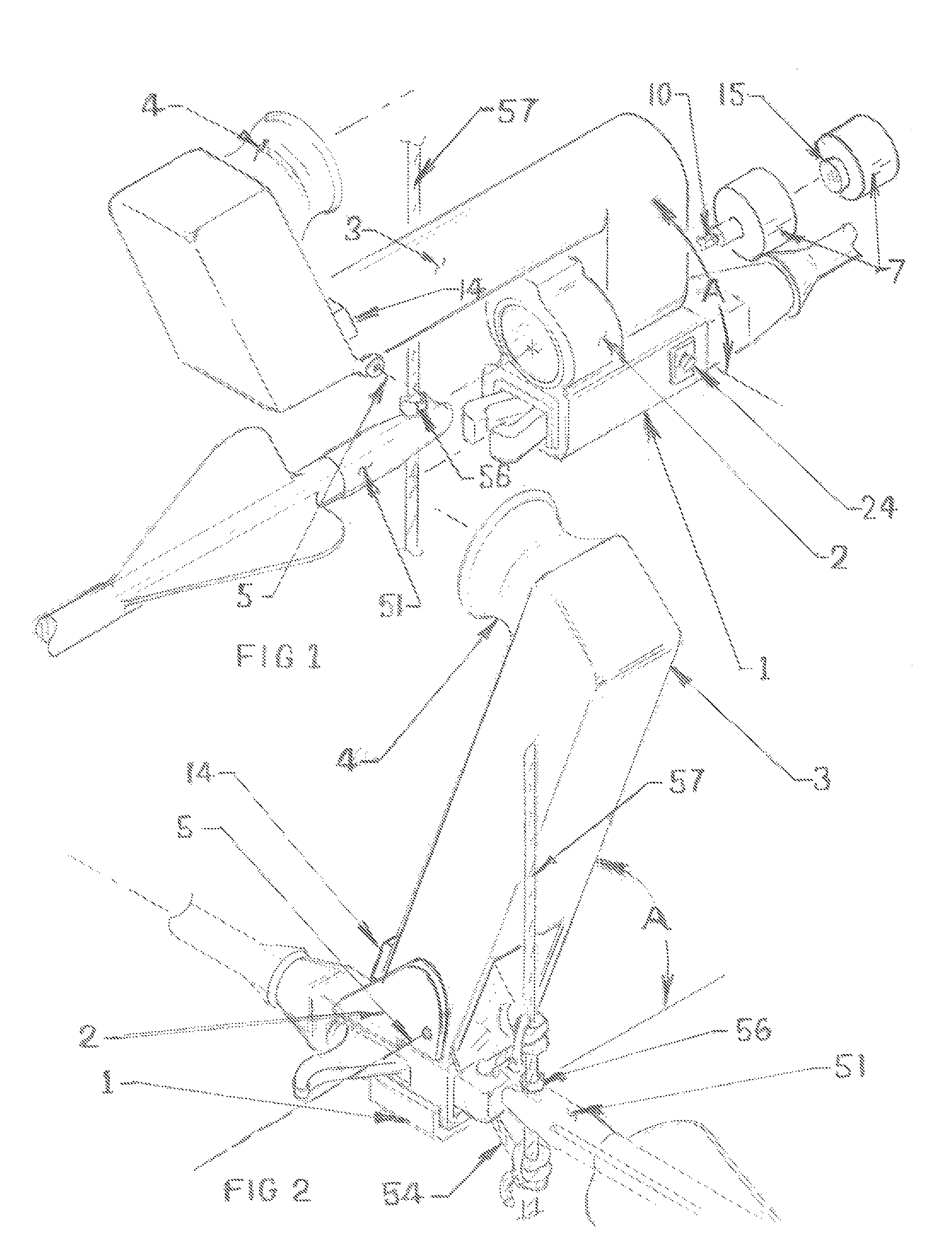
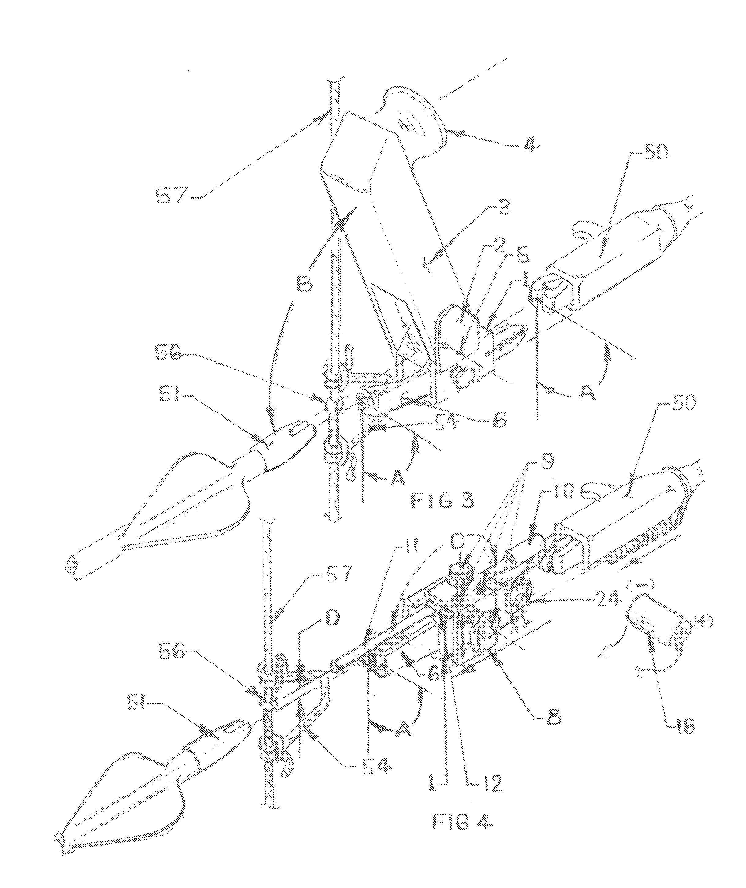
[0029]The embodiments of this invention may include a plurality of aiming devices that may be mounted onto or integrated into a Bowstring Release in a manner that enables an archer to aim along the shaft of an arrow to align the forward and rear ends of the arrow similar to aiming along the barrel of a rifle. The embodiments may enable the archer to precisely align the arrow with the target while in conventional vertical, tilted, or rotated bow shooting positions during daylight or lowlight ambient conditions. Examples of a variety of embodiments that may fulfill the functions of an Arrow Aiming Apparatus for Bow Releases are illustrated in the multiple views of the drawings and described in the Brief Description of the Drawing below.

BRIEF DESCRIPTION OF THE VIEWS OF THE DRAWINGS

[0030]Each view is identified by a [Figure—number] wherein the views illustrate examples of typical embodiments of the daylight / lowlight aiming devices and the forward and rear sighting devices that make up ...


PUM


Abstract

An offset viewing tube for daylight hours and a laser for lowlight aiming conditions are connected to a bowstring release enabling an archer to aim from behind an arrow nock along the arrow shaft similar to aiming a rifle thus eliminating parallax aiming distortion. The bow can be rotated without moving the aiming device or changing the rear elevation setting. Single pin aiming reduces confusion during setup and rushed shooting. Day or night cameras can be attached.

Description

TECHNICAL FIELDArchery[0001]This patent claims exclusive rights to an arrow aiming invention and all embodiments intended to perform the functions and claims described herein. It relates in particular to arrow sighting devices for target shooting and hunting with compound or long bows.BACKGROUND ART[0002]The first recorded arrow shooting and aiming methods were found in ancient cave art where the images depict shooters with long bows held by an extended arm with the string drawn to their chest. This was apparently the conventional draw position for centuries up to and including Native Americans. Aiming from this position is natural in that it maximizes the use of the strong muscles of the arm, chest and shoulder. However, this position presents a significant challenge to aiming an arrow. Shooting from the chest creates a significant angle between the shooter's Line of Sight (LOS) with the target and the desired trajectory of the arrow from the bow. Determining the proper arrow point...

Claims


Application Information

Patent Timeline
Patent Type & Authority Patents(United States)
IPC IPC(8): F41G1/467
CPCF41G1/467F41B5/1469F41G1/02F41G1/35F41G11/00
Inventor LEDBETTER, EMORY DAVID
Owner LEDBETTER BELINDA JANE
Why Eureka
Try Eureka