
Convective heat transfer flue

a heat transfer flue and convective technology, which is applied in the direction of fluid heaters, lighting and heating apparatus, heating types, etc., can solve the problems of large reduction of flue gas temperature, reduced flue gas velocity, and reduced flue gas temperature, so as to reduce heating surfaces, reduce flue gas velocity, and reduce flue gas temperature

Active Publication Date: 2016-09-06
MA CHENGGUO
View PDF16 Cites 0 Cited by
  • Summary
  • Abstract
  • Description
  • Claims
  • Application Information

AI Technical Summary

Benefits of technology

[0003]The technical problem to be solved by the present disclosure includes: a vortex (negative pressure) region generated on the backward surfaces of the flue gas-water heat transfer tubes swept by the flue gas is always kept unchanged in position to thus form ash deposition when the flue gas transversely sweeps over flue gas-water heat transfer tubes arranged in the convective heating surface groups, as the advancing direction of the flue gas in the convective heat transfer flue is non-adjustable; and dew can be formed easily at a rated flue gas velocity, since the flue gas temperature is greatly reduced after the flue gas interacts with a leading portion of the convective heating surface group in the flue wall, and then the flue gas temperature becomes too low when the flue gas reaches a trailing portion of the heating surface group, as the velocity of the flue gas entering the convective heat transfer flue is non-adjustable; and as the heating surface area of the convective heating surface groups swept by flue gas is non-adjustable, the flue gas is at a relatively low temperature in the starting-up phase or a low-load operation process of the boiler and however needs to sweep all the convective heating surface groups, thereby resulting in a continuous significant reduction of the flue gas temperature, and then when the flue gas reaches the tail heating surface in the flue wall, the flue gas temperature is the lowest to form dew on the tail heating surface.
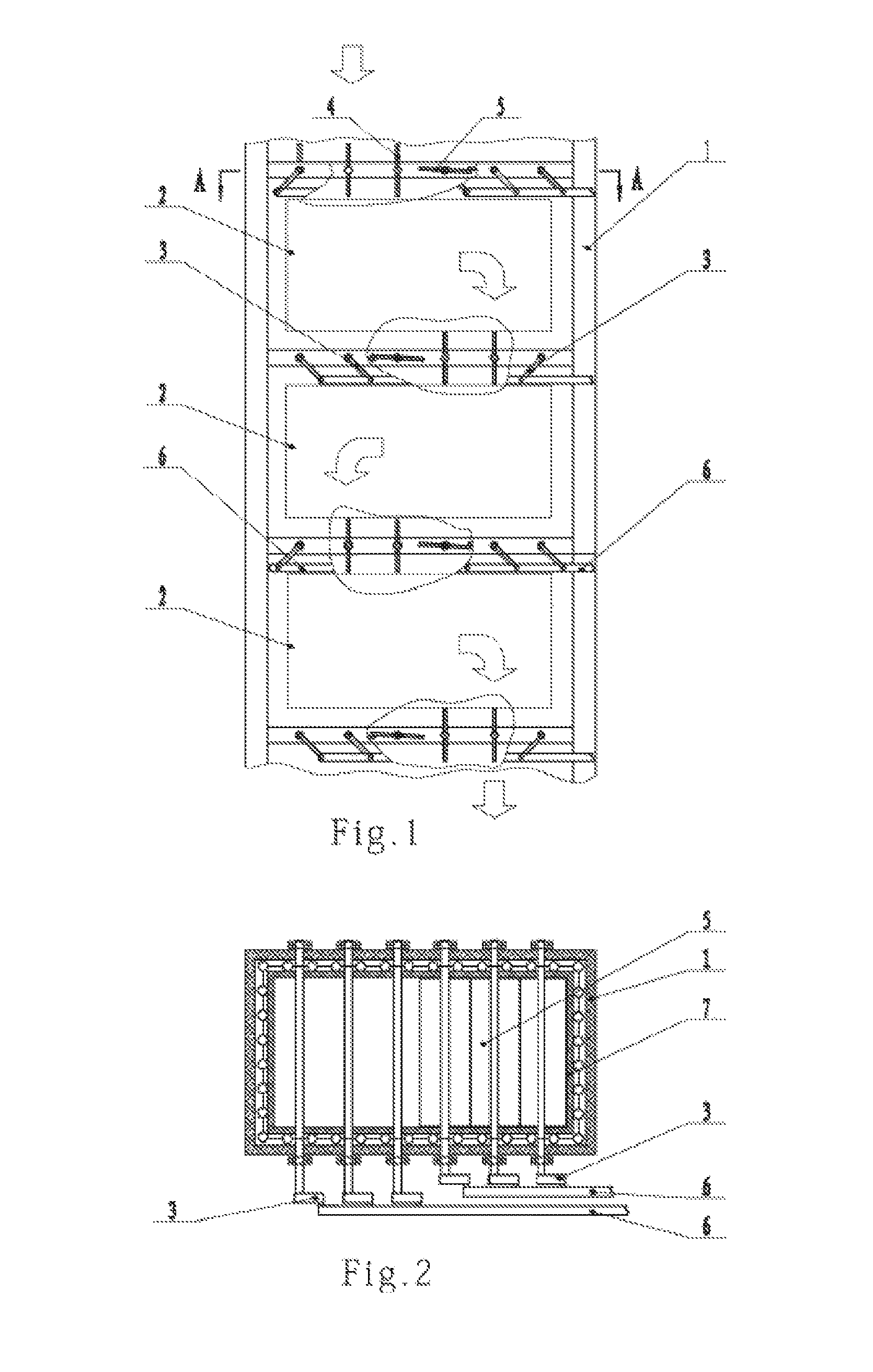
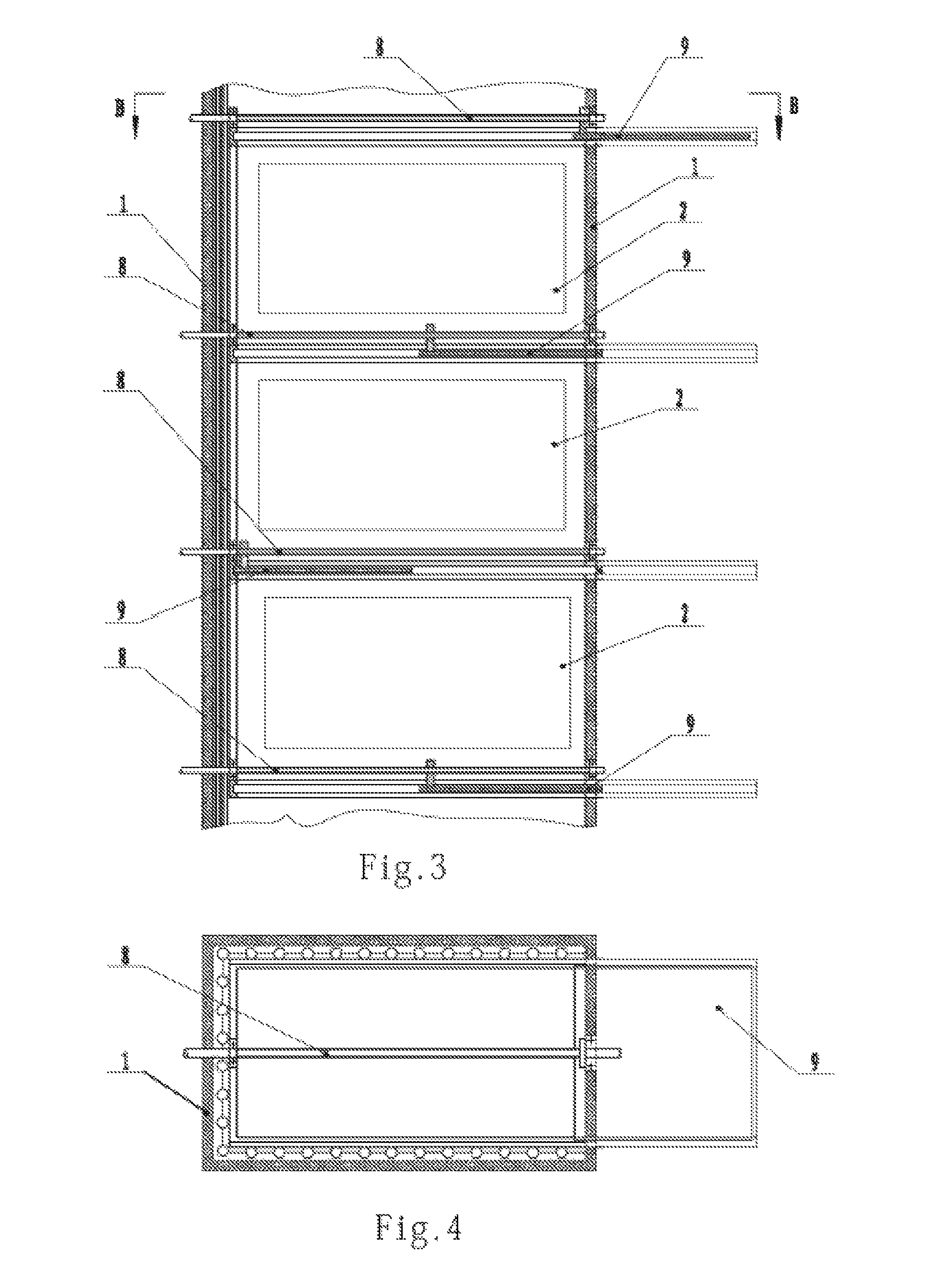
[0007]Due to the shutter or sliding gate structure design, the present disclosure may provide a beneficial effect as follows over prior arts. Firstly, when the shutters or sliding gates are regularly switched to be opened and closed on the left side and on the right side, combined with vertically offset opening and closing, the flue gas is travelled in each flue segment with a travelling direction regularly alternated between a leftward travelling direction and a rightward travelling direction. Thus, when the flue gas transversely sweeps over flue gas-water heat transfer tubes arranged in the convective heating surface groups, the backward surfaces of the flue gas-water heat transfer tubes where a vortex (negative pressure) is generated may be used as “front faces” so that the previously deposited ash may be blown away, thereby resisting ash reposition. Secondly, when all shutters or sliding gates are completely or fully opened, the travelling path of the flue gas in the controllable multidirectional-flow convective heat transfer flue is a straight cylindrical path with a large section. When the flue gas enters at a rated velocity into the controllable multidirectional-flow convective heat transfer flue, the flue gas velocity decreases and the flue gas temperature is not greatly reduced, and therefore the temperature is not too low to form dew when the flue gas reaches the tail heating surface in the flue wall. Thus, dewing resistance is realized. Thirdly, when the shutters or the sliding gates are synchronously and partially closed, the flue gas only partially sweeps over each one of the convective heating surface groups in the controllable multidirectional-flow convective heat transfer flue and the heating surfaces are reduced. Thus, in the starting-up phase or low-load operation process of the boiler, the flue gas at a relatively low temperature is prevented from a high degree of reduction in temperature. Then, dew formation on the tail heating surface can be avoided when the flue gas reaches the tail heating surface in the flue wall, namely dewing resistance is realized. Meanwhile, it is advantageous for starting up of the boiler, and a big adjustment of the load of the boiler, i.e., load tracking. As a result, the damage due to mismatch between the capacity of the boiler and the load amount can be avoided.

Problems solved by technology

As the advancing direction of the flue gas in the convective heat transfer flue is non-adjustable, it leads to a defect that, when the flue gas transversely sweeps over flue gas-water heat transfer tubes arranged in the convective heating surface groups, a vortex (negative pressure) region generated on the backward surfaces of the flue gas-water heat transfer tubes swept by the flue gas is always kept unchanged in position to thus form ash deposition.
As the velocity of the flue gas entering the convective heat transfer flue is non-adjustable, it leads to a defect that, at a rated flue gas velocity, the flue gas temperature is greatly reduced after the flue gas interacts with a leading portion of the convective heating surface group in the flue wall, and then the flue gas temperature becomes too low when the flue gas reaches a trailing portion of the heating surface group, so that dew can be formed easily.
As the heating surface area of the convective heating surface groups swept by flue gas is non-adjustable, it leads to a defect that, the flue gas is at a relatively low temperature in the starting-up phase or a low-load operation process of the boiler and however needs to sweep all the convective heating surface groups, thereby resulting in a continuous significant reduction of the flue gas temperature, and then when the flue gas reaches the tail heating surface in the flue wall, the flue gas temperature is the lowest to form dew on the tail heating surface.

Method used


Image

  • Convective heat transfer flue
  • Convective heat transfer flue
  • Convective heat transfer flue

Examples


Embodiment Construction

[0012]Preferred embodiments of the present disclosure are given below with reference to the accompanying drawings.

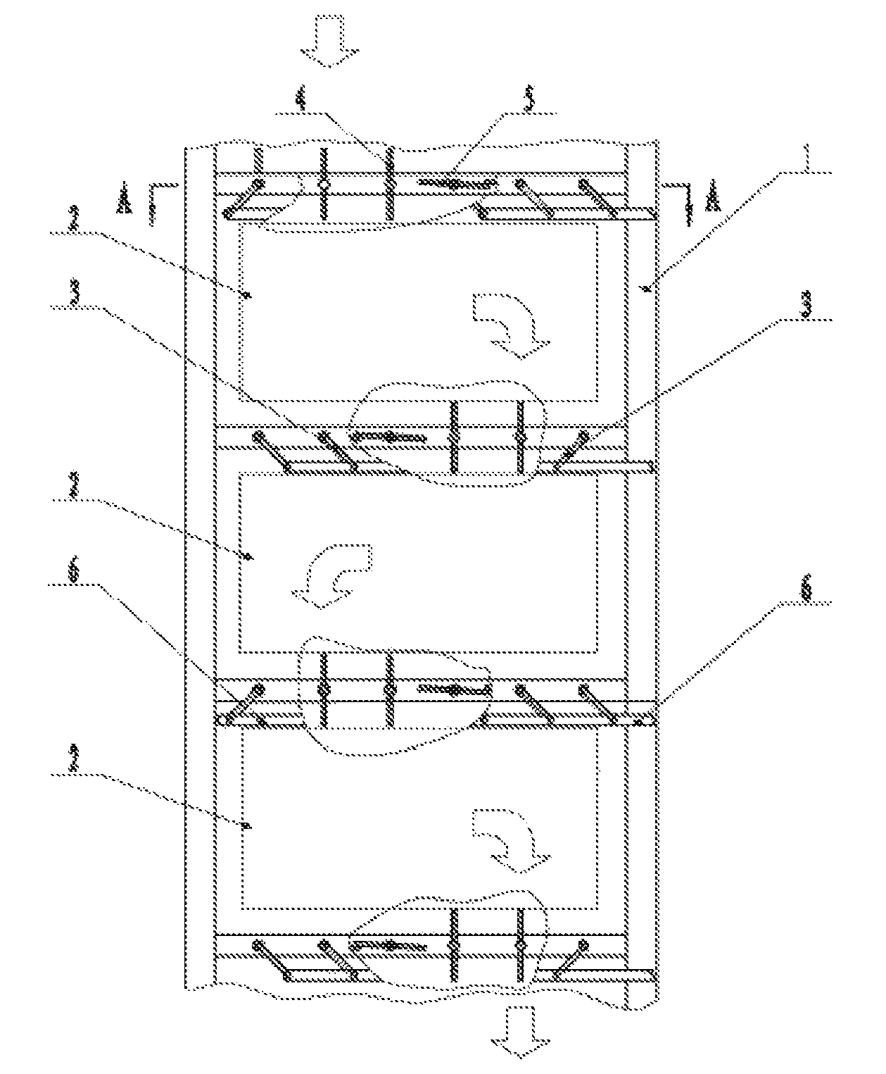
[0013]A controllable multidirectional-flow convective heat transfer flue capable of resisting fouling or ash deposition, and of resisting dewing and of tracking load, as shown in FIGS. 1 and 2, includes a flue wall 1 and convective heating surface groups 2 arranged inside the flue wall 1. Between adjacent convective heating surface groups 2, as well as at a flue gas inlet and a flue gas outlet of each convective heat transfer flue segment, there are arranged a layer of shutters which are adjustable within a range of 90 degrees. Each layer of shutters may be divided into a left group of shutters 4 and a right group of shutters 5. A frame 7 for carrying shutters is fixed to an inner side of the flue wall 1. An actuation mechanism allowing the shutters to rotate by 90 degrees includes a swing rod 3 and a connecting rod 6. The swing rod 3 is coupled to an end of a respective...


PUM


Abstract

A convective heat transfer flue, including a flue wall (1) and convective heating surface groups (2) arranged inside the flue wall (1), shutters adjustable through 90 degrees or sliding gates (9) are arranged between adjacent convective heating surface groups and at a flue gas inlet and a flue gas outlet of the convective heat transfer flue. The proposed flue solves the problems of fouling within back-flow vortex regions of heat transfer pipes, and condensation on heating surfaces in the tail of the flue wall (1), as well as being beneficial for boiler start-up and load adjustment thereof.

Description

TECHNICAL FIELD[0001]The present disclosure relates to a convective heat transfer flue of a boiler, and in particular to a controllable multidirectional-flow convective heat transfer flue capable of resisting fouling or ash deposition and resisting dewing and capable of tracking load.BACKGROUND[0002]The prior convective heat transfer flue of a boiler is just composed of a flue wall and convective heating surface groups arranged in the flue wall. Flue gas in a furnace enters the convective heat transfer flue via a flue gas inlet of the convective heat transfer flue and advances to a flue gas outlet of the convective heat transfer flue. The travelling path of the flue gas is a straight cylindrical path with a fixed section, with the advancing direction of the flue gas, the flue gas velocity and the zones of the convective heating surface groups swept by the flue gas non-adjustable. As the advancing direction of the flue gas in the convective heat transfer flue is non-adjustable, it le...

Claims


Application Information

Patent Timeline
Patent Type & Authority Patents(United States)
IPC IPC(8): F22B7/18F24H9/00F24D19/08
CPCF24H9/0031F24D19/083F23J11/00F23L11/00F22B7/18F24H9/00F28F19/00
Inventor MA, CHENGGUO
Owner MA CHENGGUO
Learn More