Drive belt for transmitting a drive movement, and method for producing a drive belt

a technology of drive movement and drive belt, which is applied in the direction of driving belt, v-belt, rope/pulley cable, etc., can solve the problems of reduced flexibility failure of the drive belt, and increased bending modulus, so as to increase the mechanical abrasion resistance of the drive belt 1, and reduce the wear ra

Active Publication Date: 2016-09-13
ARNTZ BET GMBH & CO
View PDF26 Cites 0 Cited by
  • Summary
  • Abstract
  • Description
  • Claims
  • Application Information

AI Technical Summary

Benefits of technology

[0028]As may be seen particularly from FIG. 2 there are a plurality of spaced-apart carbon cords 3 arranged cross to the belt axial direction L. This plurality of carbon cords will increase the strength of the belt body 2 even further in belt axial direction L. Also is the drive belt 1 given substantially identical physical properties cross to said belt axial direction L.
[0029]The belt body 2 is made of a curable flexible material, in particular polyurethane. The coating 4 of the belt body 2 is multi-layered. A first layer 7 in contact with the belt body 2 is a fabric layer which serves to increase the mechanical abrasion resistance of the drive belt 1 and to reduce the wear rate thereof. A second layer 8 is a polyethylene layer disposed on a flat side of the fabric layer 7 that is facing away from the belt body. Said polyethylene layer 8 may be a sheeting (polyethylene sheet) and primarily serves to reduce friction between the drive belt 1 and a not-shown belt pulley. Said closed polyethylene layer 8 keeps the flexible material for the belt body 2 from penetrating through free spaces of the fabric layer 7 and from getting into a direct contact with a belt pulley. Such direct contact of the flexible material of the belt body 2 with a belt pulley made of what are customary belt pulley materials would result in an unacceptably high friction coefficient of for instance 0.6 or over. The friction reducing polyethylene layer prevents such a direct contact of the flexible material with a belt pulley. A friction coefficient between said polyethylene layer 8 and the belt pulley material is typically 0.4 or less. The two-layer version of the coating 4 has been given for example only while said coating 4 of the invention may as well comprise more than two such layers or consist of just one layer such as a fabric layer 7 or the polyethylene layer 8.

Problems solved by technology

The drawback involved in this case is that the polyurethane contained inside the carbon fiber cavities makes the drive belt undesirably hard after curing which means that penetration of polyurethane into the carbon cord reduces the flexibility of the drive belt and increases the bending modulus thereof with the consequence that the carbon cord would be exposed to unacceptably severe loads as it turns around belt pulleys which might cause damages to (in particular ruptures of) the carbon cords and hence give rise to failures of the drive belt and a reduction of service life thereof.

Method used


Image

  • Drive belt for transmitting a drive movement, and method for producing a drive belt
  • Drive belt for transmitting a drive movement, and method for producing a drive belt

Examples


Embodiment Construction

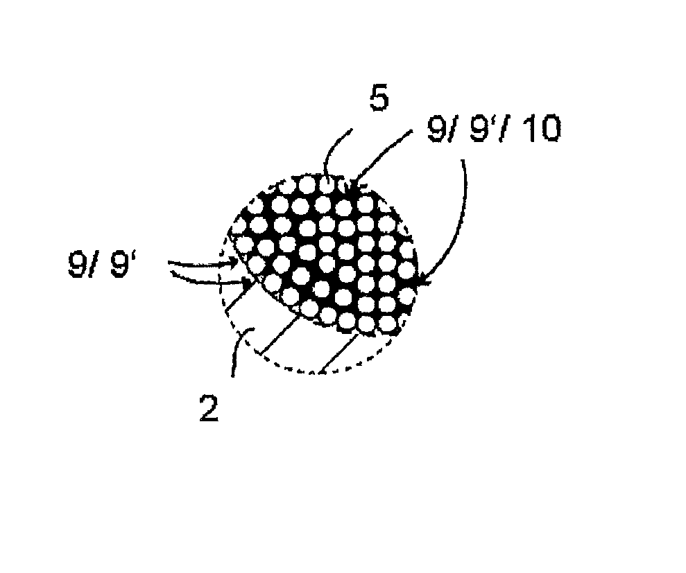
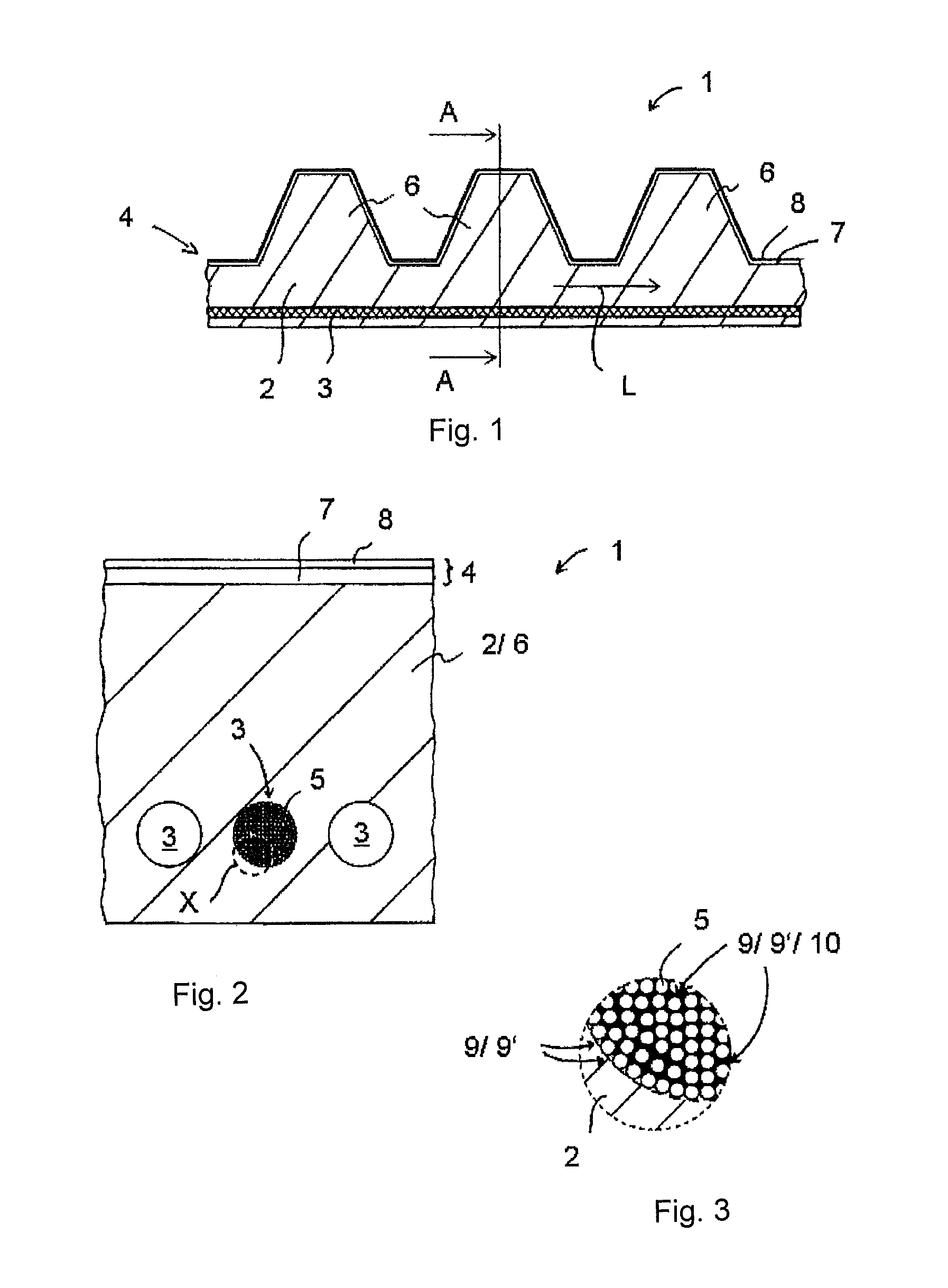
[0033]A plurality of carbon fibers 5 are twisted into a yarn to make a carbon cord 3. Said carbon fibers are immersed into a dipping bath for applying and / or introducing the rupture risk reducing filler 10. The rupture risk reducing filler 10 adheres to the carbon fibers 5 and / or fills up the first portion 9′ of the cavities while being immersed. The process steps of twisting and immersing the carbon fibers 5 may be performed in any desired order. To meet the requirements of a specific application it is possible also to twist two or more yarns into a yarn bundle. Such twisting of two or more yarns into a yarn bundle in turn may be effected before or after immersing the carbon fibers 5 into the dipping bath.

[0034]Another process step in forming the belt body 2 is to wrap a carbon cord 3 containing the rupture risk reducing filler 10 with curable flexible material and to make part of said material penetrate into the second portion 9″ of those cavities 9 which are not containing any ru...


PUM


Abstract

A drive belt having a belt body which is made of a flexible material and a tensile reinforcement that extends in belt axial direction and which is surrounded by said belt body in sections at least to improve the tensile strength of the body in belt longitudinal direction wherein the tensile reinforcement is a carbon cord made of a plurality of twisted carbon fibers with a plurality of cavities between the fibers which are charged with a filler material in part at least. A first portion of the carbon fiber cavities is charged with a rupture risk reducing filler of a type different from the belt body flexible material and a second portion of said cavities of the carbon fibers is filled with belt body flexible material. The carbon cord has less than 0.2 mg of belt body flexible material per one millimeter3 cord volume.

Description

BACKGROUND OF THE INVENTION[0001]1. Field of the Invention[0002]This present invention relates to a drive belt having a belt body which is made of a flexible material and a tensile reinforcement that extends in belt axial direction and which is surrounded by said belt body in sections at least to improve the tensile strength of the body in belt longitudinal direction wherein the tensile reinforcement is a carbon cord consisting of a plurality of twisted carbon fibers with a plurality of cavities between said fibers which are filled with a filler material in part at least.[0003]2. Description of the Related Art[0004]The invention also relates to a process for making a drive belt, which has a belt body made of a flexible material and carbon cords surrounded by said belt body in sections at least and extends in a belt longitudinal direction to improve the tensile strength of the body wherein the carbon cords consist of a plurality of carbon fibers which are twisted into a yarn and embe...

Claims


Application Information

Patent Timeline
Patent Type & Authority Patents(United States)
IPC IPC(8): F16G1/00B29D29/08F16G1/16F16G1/10F16G1/08F16G5/20F16G1/28F16G9/00F16G5/00
CPCF16G1/10B29D29/08F16G1/08F16G1/16F16G1/28F16G5/20
Inventor GIBSON, DANIEL PATTIE
Owner ARNTZ BET GMBH & CO
Why Eureka
Try Eureka