Switch mode power supply module and associated hiccup control method

a technology of power supply module and hiccup control, which is applied in the direction of electric variable regulation, process and machine control, instruments, etc., can solve the problems of not being able to detect the absence of load autonomously, and requiring built-in intelligen

Active Publication Date: 2016-09-13
INTERDIGITAL MADISON PATENT HLDG
View PDF35 Cites 5 Cited by
  • Summary
  • Abstract
  • Description
  • Claims
  • Application Information

AI Technical Summary

Benefits of technology

[0010]The invention enables at least one of the disadvantages of the prior art to be resolved by enabling automatically and autonomously the input and the output in a no-load mode with intermittent interruption of the switching operation, and by authorizing a low residual consumption without recourse to control from the powered equipment (signal or message).

Problems solved by technology

The detection of absence of load is however not autonomous and the switching operation is controlled using a control signal set up by the powered equipment connected to the switch mode power supply.
This solution has the disadvantage of requiring built-in intelligence on the powered equipment to control the no-load mode and a specific conductor or a mode of communication by current or voltage modulation between the power supply module and the powered equipment.

Method used


Image

  • Switch mode power supply module and associated hiccup control method
  • Switch mode power supply module and associated hiccup control method
  • Switch mode power supply module and associated hiccup control method

Examples


Embodiment Construction

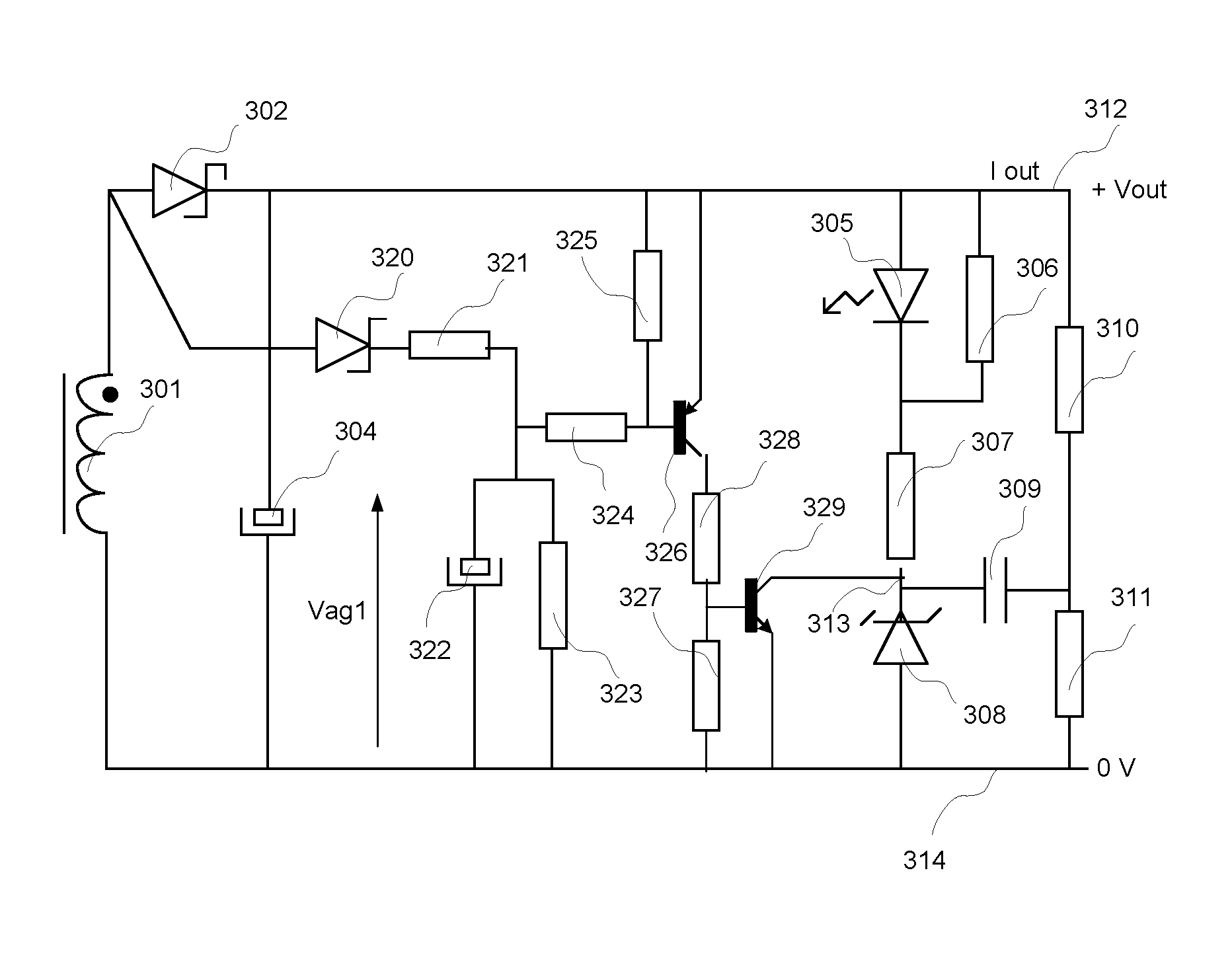
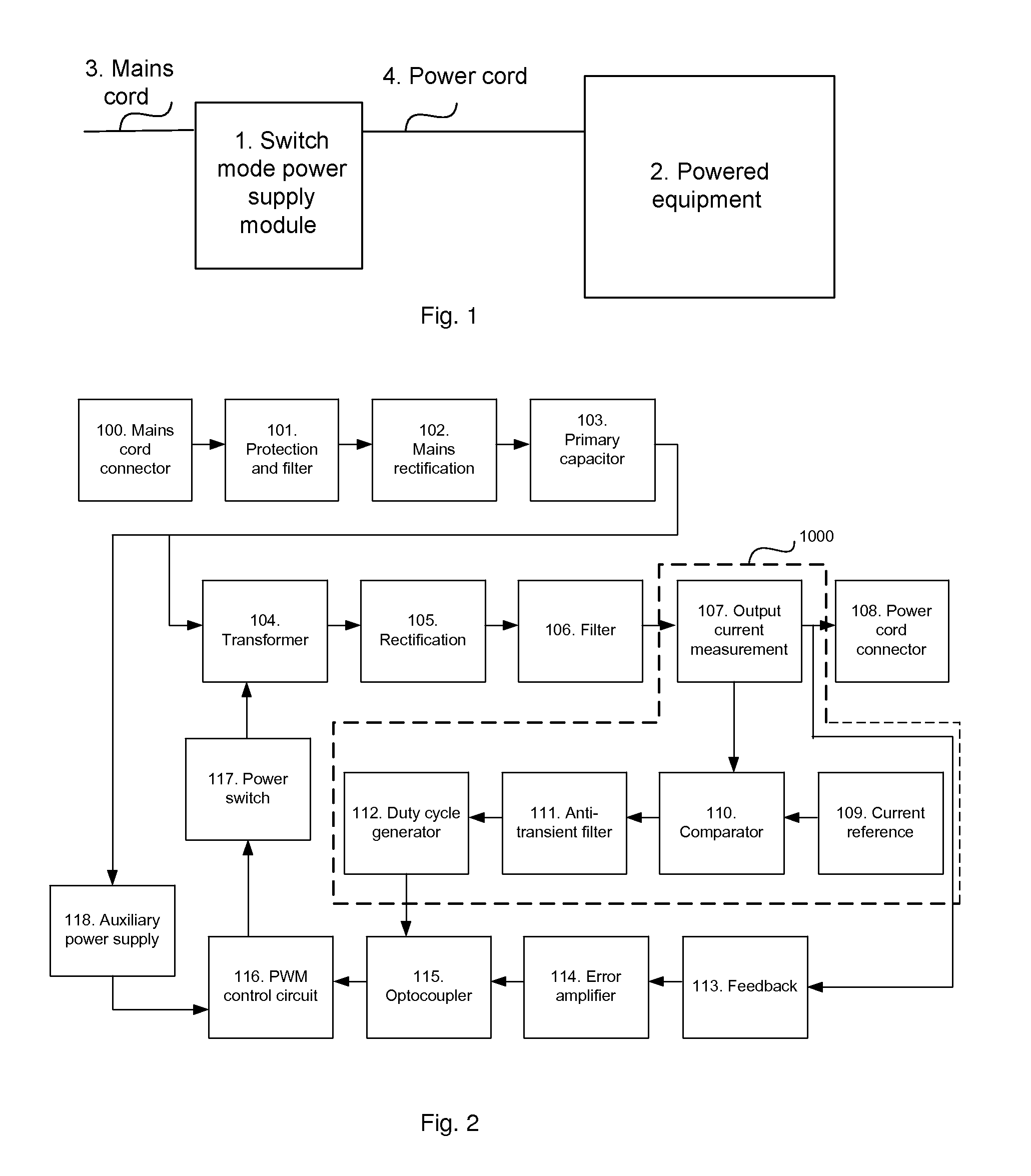
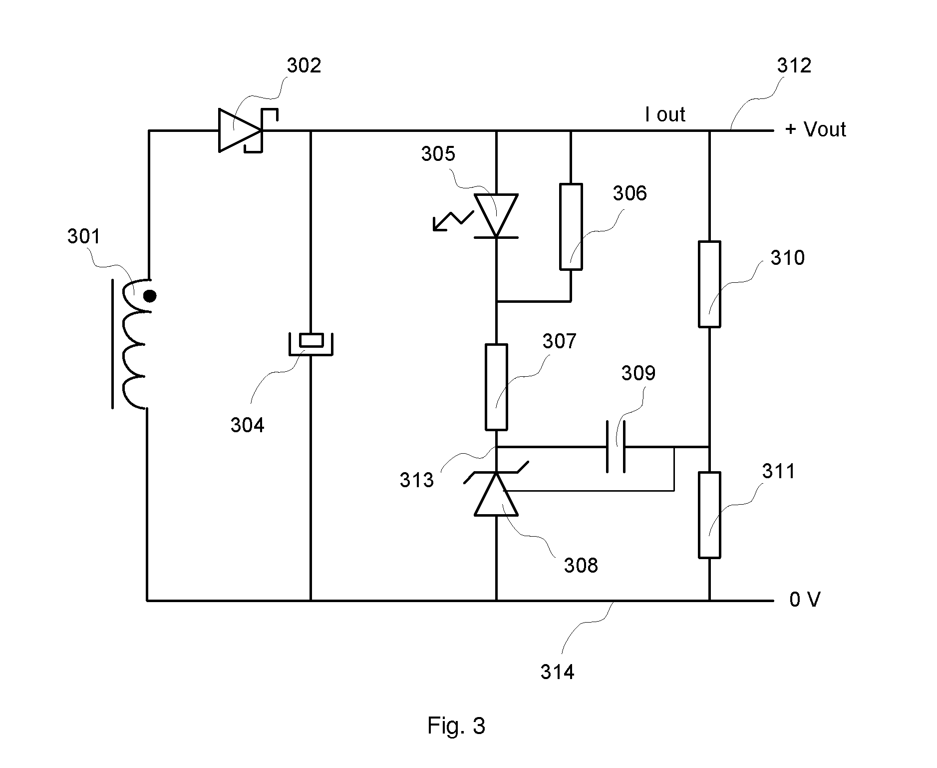
[0034]In FIGS. 1 to 5, the modules shown are functional units that may or may not correspond to physically distinguishable units. For example, these modules or some of them are grouped together in a single component, or constitute functions of the same software. On the contrary, according to other embodiments, some modules are composed of separate physical entities.

[0035]In the present document, the terms “cyclically interrupting the switching operation” or “even interrupting the switching operation” should not be associated to the interval of time when between two consecutive pulses of the switching control in a Pulse Width Modulation (PWM) mode (time between two consecutive pulses when the frequency of pulses in PWM is very low). It should also not be interpreted as the interval of time when, in case of a very low load current, some pulses are removed as already known in the prior art.

[0036]The terms “interrupting the switching” correspond to a state in which the switching control...


PUM


Abstract

The invention concerns a method and device for controlling the switching operation in a switch mode power supply module. The switch mode power supply module is intended to supply power to an item of equipment. The method comprises the steps of measuring, in the switch mode power supply module, the load current and comparing the measured load current with a predefined load current threshold value, and, cyclically interrupting the switching operation if the measured load current inside the device is less than the predefined load current threshold value.

Description

[0001]This application claims the benefit, under 35 U.S.C. §119 of FR Patent Application 1251274, filed 10 Feb. 2012.1. DOMAIN OF THE INVENTION[0002]The invention relates to the domain of switch mode power supply modules and more specifically to integrated power supply.2. PRIOR ART[0003]Traditionally, when an external power supply module is used (commonly called DC-PACK or DC power block), the operating mode corresponding to the lowest consumption is implemented when the connection with the load is cut (load disconnected or switch in the open position). When the external power supply module is connected to the mains, a residual consumption remains.[0004]The commercialization of electronic equipment today requires compliance with power consumption directives.[0005]Thus in Europe the EC / 278 / 2009 directive requires a level of power consumption less than 0.3 W for power supplies delivering a nominal power less than 51 W.[0006]Theoretically, power supplies using PFM (Pulse Frequency Modu...

Claims


Application Information

Patent Timeline
Patent Type & Authority Patents(United States)
IPC IPC(8): H02M3/156H02M3/22H02M5/458H02M3/337H02M3/335H02M1/42H02M1/36H02M1/00
CPCH02M3/22H02M1/36H02M3/156H02M3/335H02M2001/0035Y02B70/16Y02B70/10H02M1/0035H02M3/28
Inventor MARCHAND, PHILIPPEMORIZOT, GERARDGUILLOT, PHILIPPE
Owner INTERDIGITAL MADISON PATENT HLDG
Why Eureka
Try Eureka