

Golf club shaft fitting method
a golf club and shaft technology, applied in the field of golf club shaft fitting methods, can solve problems such as lack of unified standards
- Summary
- Abstract
- Description
- Claims
- Application Information
AI Technical Summary
Benefits of technology
Problems solved by technology
Method used
Image

Examples
first embodiment
Principle of Fitting Method of Present Invention
[0148]Before describing embodiments of the fitting method of the present invention, the principle or theoretical background of the fitting method of the present invention will be described. The present inventors have focused on the fact that bending of a shaft of a golf club travels from a hand side to a front end side of the shaft as a swing proceeds from the top to the impact. Then, as a result of conducting thorough research and examination under an assumption that there is a correlation between swing characteristics (details of the swing characteristics will be described later), of a certain golfer, associated with the course of time from the top to the impact and hardness in every inch of a shaft matching the golfer, the present inventors have accomplished the present invention.
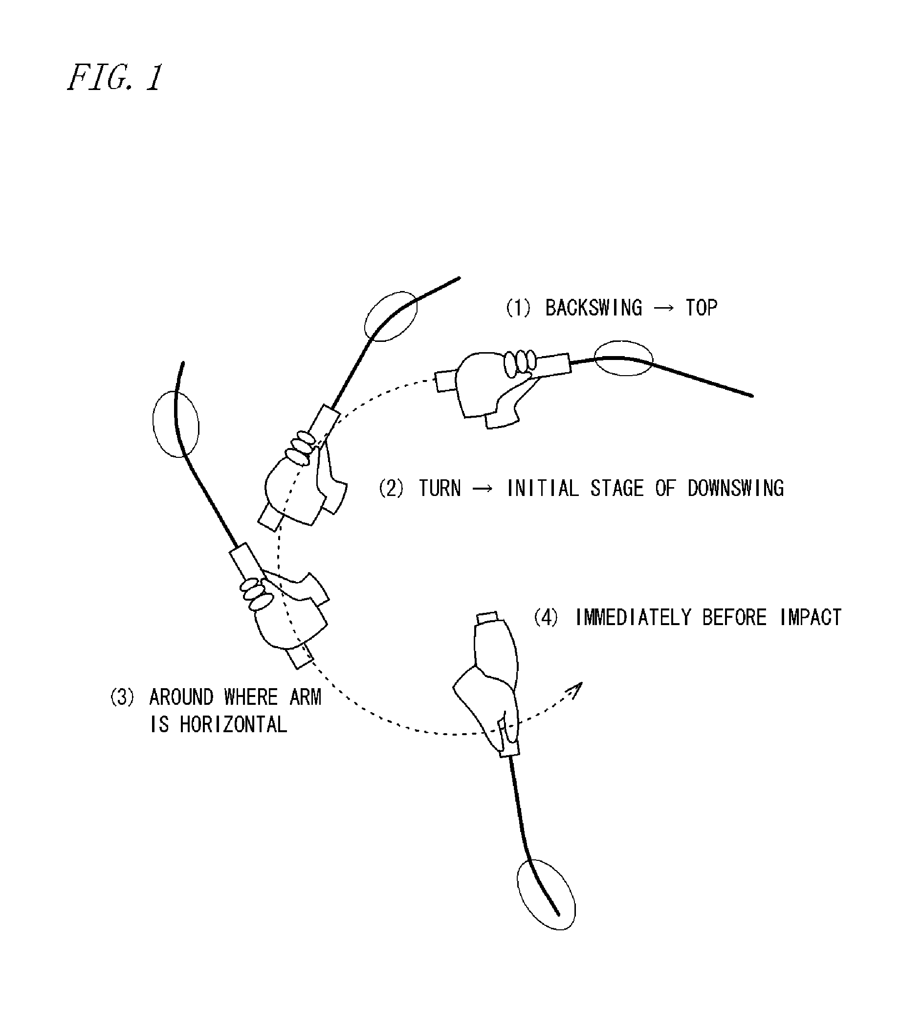
[0149]That is, a swing of a golfer when hitting a ball transitions from the address to top and to impact, and, at that moment, since a head having a relati...
second embodiment
[0268]In a second embodiment, unlike the first embodiment described above, bending stiffnesses at three measurement points of the shaft 20 are measured and converted into numerical values.
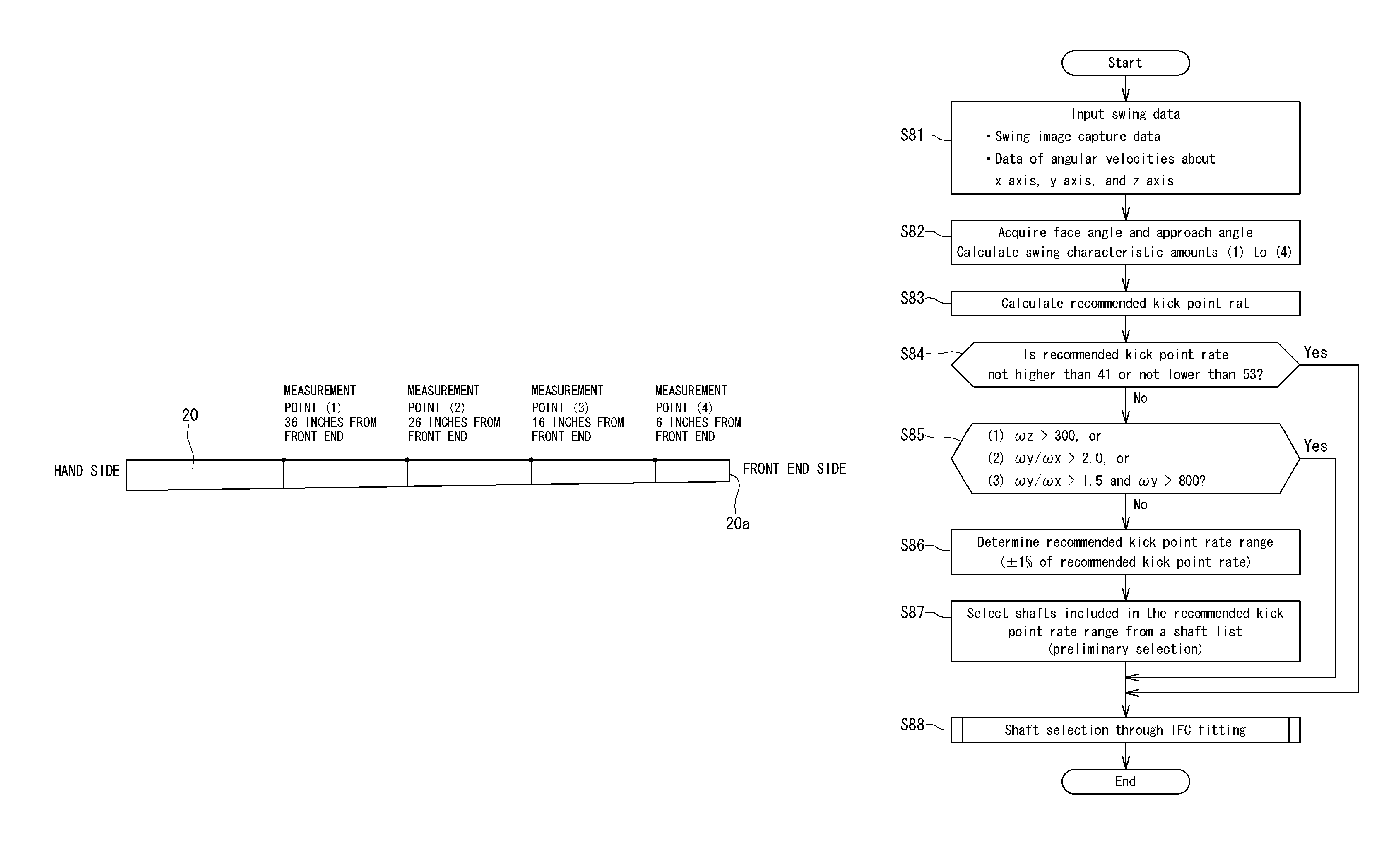
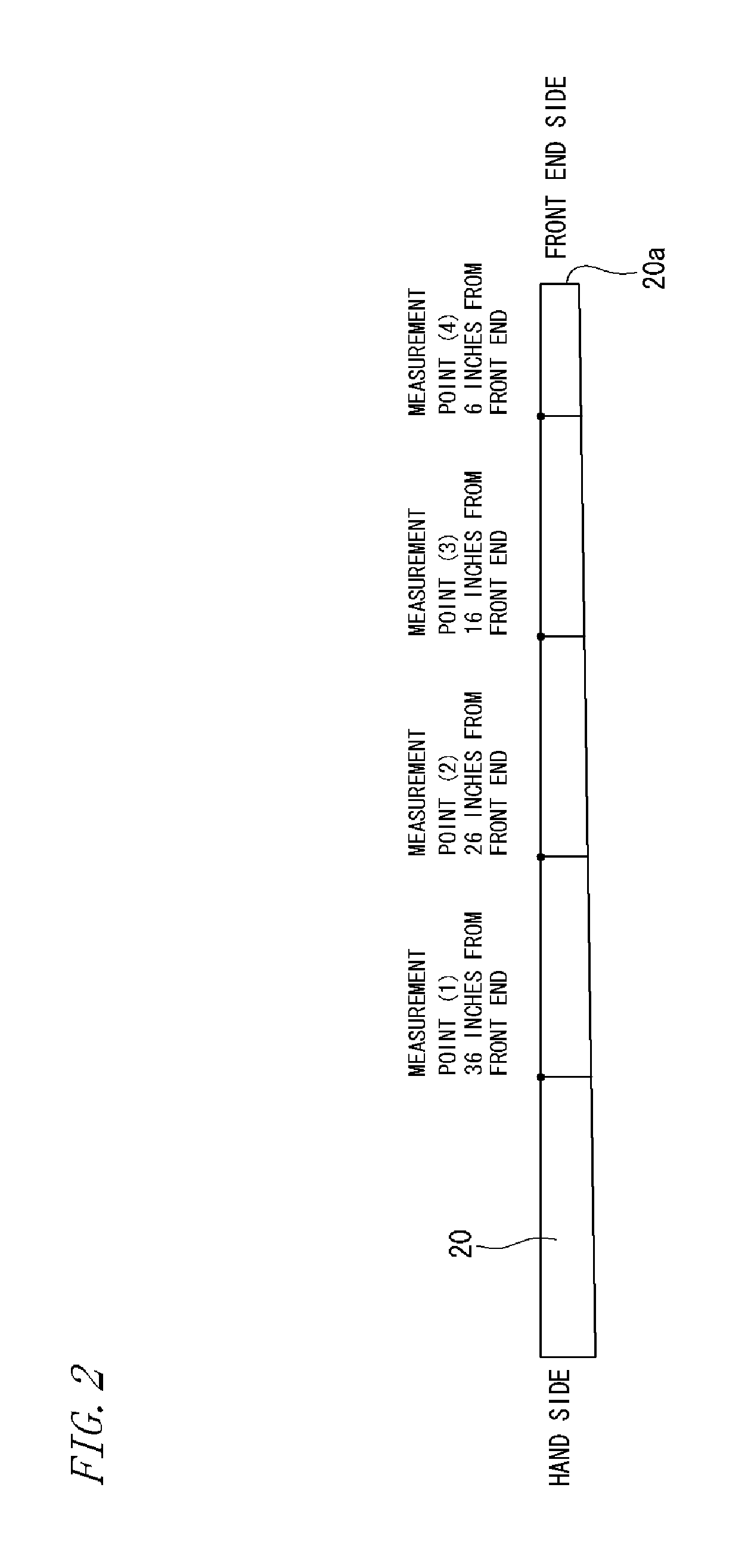
[0269]Specifically, as shown in FIG. 30, the shaft 20 is divided into three regions, and bending stiffness at a single point in each of the regions is defined. In the present embodiment, with respect to the tip end 20a of the shaft 20, a part 36 inches therefrom is defined as a measurement point (1), a part 26 inches therefrom is defined as a measurement point (2), and a part 6 inches therefrom is defined as a measurement point (3). Then, bending stiffnesses at the three measurement points of the shaft 20 are measured and converted into numerical values. It should be noted that, in the present specification, “every inch” does not mean “at 1 inch, at 2 inches, etc.,” but means “every part of a plurality of parts whose distances from one end of a shaft are predetermined inches;” and “predetermined in...
third embodiment
Fitting Apparatus
[0352]First, a fitting apparatus capable of using the fitting method according to the present embodiment will be described.
[0353]FIG. 39 is an illustrative diagram of a fitting apparatus 102 used for the fitting method of the present invention. The fitting apparatus 102 is a fitting apparatus for right-handed golfers, and includes: a front camera 104 and an upper camera 106 as image capturing sections; a first sensor 108 including a light emitter 114 and a light receiver 116; a control device 110; and an information processing device 112 as a computation section.
[0354]The front camera 104 is located in the front of a golfer who is to perform a swing, and is arranged in a direction and position allowing capturing of a swing image from the front of the golfer. On the other hand, the upper camera 106 is located above a position where a ball B is placed, and is arranged in a direction and position allowing capturing of a swing image from above the golfer. Examples of th...
PUM
 Abstract
Description
Claims
Application Information