Method for air entry in liner to reduce water requirement to control NOx

a liner and air entry technology, applied in continuous combustion chambers, combustion processes, lighting and heating apparatus, etc., can solve the problems of limited in its ability to achieve low levels of pollutants, unsatisfactory, and high temperature in combustion chamber primary zones, so as to reduce the temperature and nox emissions, reduce the water requirement, and reduce the cooling of the liner

Inactive Publication Date: 2016-09-27
GENERAL ELECTRIC CO
View PDF14 Cites 0 Cited by
  • Summary
  • Abstract
  • Description
  • Claims
  • Application Information

AI Technical Summary

Benefits of technology

[0008]The present invention seeks to reduce water requirements in conventional combustors to reduce temperatures and NOx emissions when operating on NG / LF or syngas fuels. In the present invention, combustion in a conventional combustor is changed from “rich to lean” to “rich to quench to lean” by changing the air entry arrangement in the liner of the conventional combustor. In this changed air entry arrangement, dilution holes are removed, liner cooling is reduced and dilution air is admitted into the combustor liner in place of mixing air admitted into the combustor liner through a third row of mixing holes. In an alternative embodiment, dilution air is admitted into the combustor liner with the help of a plurality of pipes arranged in such a manner so that such air comes into the liner as a swirling flow in a direction opposite to nozzle swirl, so as to thereby produce a large mixing of air with the combustion gases and a resulting quenching effect, i.e., a rapid cooling of the combustion gases by quenching air. As such, the requirement for cooling water to quench the combustion gases is significantly reduced, thereby helping in turbine efficiency and a reduction in turbine emissions.
[0009]The present invention reduces temperatures in the primary reaction zone of a combustor by moving dilution air upstream and providing swirl to incoming air to enhance mixing. Reduction in temperature leads to reduction in NOx generation which is very high in conventional liners before combustion gases reach the dilution holes in the combustor. The present invention also reduces the cooling water requirement in conventional liners, which is typically very high.
[0010]In a first embodiment of the present invention, a combustor operating with a compressor to drive a gas turbine is comprised of an outer combustor wall having an upstream fuel entry end and a downstream turbine entry end; a plurality of mixing holes located proximal to the upstream fuel entry end of the outer combustor wall; and a plurality of dilution holes located proximal to the plurality of mixing holes to admit air into a combustion zone in the combustor for mixing of the admitted air with combustion gases in the combustion zone to thereby reduce NOx and carbon monoxide (CO) production in the combustion zone.
[0011]In another embodiment of the present invention, a combustor operating with a compressor to drive a gas turbine is comprised of an outer combustor wall having an upstream fuel entry end and a downstream turbine entry end; a plurality of mixing holes located proximal to the upstream fuel entry end of the outer combustor wall, the plurality of mixing holes being arranged in a plurality of rows which extend around a circumference of the outer combustor wall; and a plurality of dilution holes arranged in one or more rows which extend around the circumference of the outer combustor wall, the plurality of dilution holes being located proximal to the plurality of mixing holes; an outer shell; a nozzle from which compressed air and fuel are discharged into combustor; a flow sleeve located between the outer shell and the combustor wall so as to form a cavity between the outer shell and the combustor wall so that air from the compressor entering the combustor is divided between a first path by which a first part of the compressor air is admitted into the combustor by entering through the flow sleeve, and a second path by which a second part of the compressor air is admitted into the combustor through the cavity; and a plurality of pipes extending between the cavity and the plurality of dilution holes to admit the second part of the compressor air into the combustion zone for increased mixing of the admitted air with combustion gases in the combustion zone to thereby reduce NOx and carbon monoxide (CO) production in the combustion zone.
[0012]In a further embodiment of the present invention, a combustor operating with a compressor to drive a gas turbine is comprised of an outer combustor wall having an upstream fuel entry end and a downstream turbine entry end, the outer combustor wall having a length between 35 inches and 50 inches; a plurality of rows of liner louver cooling holes positioned longitudinally along the combustor wall; a plurality of mixing holes located proximal to the upstream fuel entry end of the outer combustor wall; the plurality of dilution holes being located proximal to the plurality of mixing holes; the plurality of mixing holes being arranged in first and second rows which extend around a circumference of the outer combustor wall rather than first, second and third rows which extend around the circumference of the outer combustor wall so that the plurality of dilution holes are arranged in the third row from the upstream fuel entry end extending around the circumference of the outer combustor wall so as to be located within a distance of five inches to forty inches from the fuel entry end of the combustor wall; an outer shell; a nozzle from which compressed air and fuel are discharged into combustor; a flow sleeve located between the outer shell and the combustor wall so as to form a cavity between the outer shell and the combustor wall so that air from the compressor entering the combustor is divided between a first path by which a first part of the compressor air is admitted into the combustor by entering through the flow sleeve, and a second path by which a second part of the compressor air is admitted into the combustor through the cavity; and a plurality of pipes extending between the cavity and the plurality of dilution holes at an angle to thereby tangentially admit the second part of the compressor air into the combustion zone for increased mixing of the admitted air with combustion gases in the combustion zone, the angle at which the pipes enter the combustor being achieved using an offset of the pipes of zero to seven inches from the center of the combustor, the diameters of the plurality of dilution holes though which air from the plurality of pipes is passed into the combustor being increased to a dimension that results in an increase in air flow into the combustor combustion chamber, and the diameters of the plurality of louver cooling holes though which louver cooling air passes being reduced to a dimension that results in a further increase in mixing of the admitted air with combustion gases in the combustion zone to thereby reduce NOx and carbon monoxide (CO) production in the combustion zone.

Problems solved by technology

Thus, temperatures in combustion chamber primary zones can get very high if water is not injected, although temperatures do drop along the length of the combustion chamber.
However, water or steam injection is a relatively expensive technique and can cause the undesirable side effect of quenching (i.e., rapid cooling) carbon monoxide (CO) burnout reactions, and which is limited in its ability to achieve low levels of pollutants.
But conventional combustors use a very old liner cooling design that involves the use of water or steam injection, which is not desirable in gas turbine power plants from life of components, operability and cost of electricity perspectives.
Sufficient efforts have not been made to reduce water consumption in these machines.

Method used


Image

  • Method for air entry in liner to reduce water requirement to control NOx
  • Method for air entry in liner to reduce water requirement to control NOx
  • Method for air entry in liner to reduce water requirement to control NOx

Examples


first embodiment

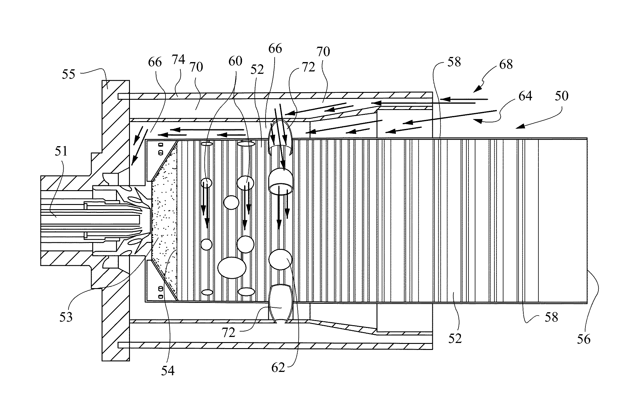
[0035]FIGS. 4A to 4C show a Dry Low NOx (“DLN”) combustion system incorporating the combustor liner 50 shown in FIG. 3. The DLN combustion system includes combustor liner 50, a nozzle 51 from which compressed air 14 and fuel 16 that is mixed with the compressed air 14 is discharged into combustor 50 and a diverging cone 53 positioned between nozzle 51 and combustor 50. An endplate 55 holds the body of the combustor 50 together.

[0036]In the preferred embodiment shown in FIGS. 4A to 4C, the mixing holes 60 are preferably arranged in two rows, which extend around the circumference of the cylindrical combustor wall 52, and which are proximate to the fuel entry end 54 of the cylindrical combustor wall 52. The dilution holes 52 are arranged in a single row, which replaces a third row of mixing holes that would typically be present in a conventional combustor. The row of dilution holes 52 preferably extends around the circumference of the cylindrical combustor wall 52, and is proximate to ...

second embodiment

[0037]FIG. 5A to 5C show a DLN combustion system incorporating the combustor 50 shown in FIG. 3. In the embodiment shown in FIG. 5A to 5C, the modified liner shown in the embodiment of FIGS. 4A to 4C is maintained. However, the embodiment shown in FIG. 5A to 5C also includes a modified cavity arrangement for much larger mixing of air with the combustion gases within the combustion chamber 28. Thus, as in the embodiment of FIGS. 4A to 4C, the dilution holes 52 are again moved to the third row of mixing holes 50 in combustor wall 62 so that dilution air is admitted into the combustor 50 at the third row of mixing holes 50, and, as such, the mixing holes 50 in the third row are removed. In the modified cavity arrangement, the mid-frame air 64 is divided into two paths, i.e., one path for a part of the mid-frame air 64 to continue to be admitted into the combustor 50 by entering through flow sleeve 66, and another path for another part 68 of the mid-frame air 64 to flow through a cavity...

third embodiment

[0038]FIG. 6A to 6C show a DLN combustion system incorporating the combustor 50 shown in FIG. 5. In the embodiment shown in FIG. 6A to 6C, the modified liner with relocated dilution holes, as shown in the embodiment of FIGS. 4A to 4C, is again used. In addition, the modified cavity arrangement for much larger mixing of air and combustion gases in the embodiment shown in FIG. 5A to 5C is again used. However, increased air flow of 10-15% is added to increase the penetration of air into the hot temperature zones in the combustion chamber 28. This is achieved by increasing the size / diameter of the dilution holes 62 though which air from pipes 72 is passed into combustor 50. Also, louver cooling air passing through the plurality of rows of louver cooling holes 58 in the combustor liner 50 is reduced by half from 25-35% of the mid-frame air flow 64 to 10-15% of the mid-frame air flow 64 by decreasing the size / diameter of the cooling holes 58. It is noted that 25-35% louver cooling is an o...


PUM


Abstract

An improved combustor is disclosed in which conventional combustion is changed to “rich to quench to lean” by changing the air entry arrangement in the liner of the combustor to remove mixing holes, reduce liner cooling and admit dilution air into the combustor liner in place of mixing air. In an alternative embodiment, dilution air is admitted into the combustor liner with the help of a plurality of pipes arranged so that air comes into the liner as a swirling flow in a direction opposite to nozzle swirl, so as to thereby produce a large mixing of air with the combustion gases and a resulting quenching effect, i.e., a rapid cooling of the combustion gases by quenching air. As such, the requirement for cooling water to quench the combustion gases is significantly reduced, thereby helping turbine efficiency and reducing turbine emissions.

Description

[0001]The present invention relates turbines, and more particularly to a method of introducing air into a gas turbine combustor to reduce combustor NOx emissions and water requirements in reducing such emissions.BACKGROUND OF THE INVENTION[0002]Gas turbine engines include a compressor for compressing air that is mixed with fuel and ignited in a combustor for generating combustion gases. The combustion gases from the combustor flow to a turbine that extracts energy for driving a shaft to power the compressor and produces output power, often for powering an electrical generator.[0003]Increased requirements for low emissions from turbine power plants now require low rates of emissions of NOx (mono-nitrogen oxides NO (nitric oxide) and NO2 (nitrogen dioxide)), CO (carbon monoxide) and other pollutants from turbine combustors.[0004]Conventional turbine combustors use non-premixed diffusion flames, where fuel and air freely enter the combustion chamber separately and mixing of the fuel an...

Claims


Application Information

Patent Timeline
Patent Type & Authority Patents(United States)
IPC IPC(8): F02C1/00F23R3/04F23R3/06
CPCF23R3/06F23R3/045
Inventor SINGH, ARJUN
Owner GENERAL ELECTRIC CO
Why Eureka
Try Eureka