System and method for linear frequency translation, frequency compression and user selectable response time

a linear frequency and response time technology, applied in the field of linear frequency translation, frequency compression and user selectable response time, can solve the problems of not allowing reliable, successful circuitry processing, and only moderately successful techniques, and achieve the effect of providing signal isolation

Active Publication Date: 2016-10-11
LANNES KENNETH JOHN
View PDF10 Cites 0 Cited by
  • Summary
  • Abstract
  • Description
  • Claims
  • Application Information

AI Technical Summary

Benefits of technology

[0011]The method and system of the present invention multiplies and sums an incoming signal with itself in the opposite direction. By doing this, this creates the affect of “two trains” (two signals) passing each other and the output signal contains all of the input frequencies doubled with no distortion or intermodulation products. This is a result of the relative movement between the two signals (two trains). This is in essence a dynamic matched filter. Although the match is not perfect in the classical sense of matched filtering, it is extremely effective and provides isolation of the signal. Matched filtering is well known in the art. Furthermore, the present invention has no issues of any kind with respect to data overflows or voids in realtime. The method is comprised of multipliers and summers and shift registers, or memory locations if preferred, and is shown in FIG. 1. The power of this method is that a frequency can enter the multiply / sum window and there will be no output until the signal “sees itself” coming in from the other direction, even if a previous, different frequency is previously left over in the multiply-sum window. The new frequency is orthogonal to the previous frequency since they are different and will not give an output until it sees its own “image”, or matched response coming from the other direction. The rise time of each individual frequency is proportional to the multiply-sum window length. So no matter how many frequencies are input simultaneously, and no matter how much their amplitudes may vary, there will be no output due to any individual frequency until it is “matched” with its mirror image entering the window from the opposite side. Each frequency will have its own slow attack (much like a violin) without the necessity of any analog type processing based on thresholding or frequency measurement. This has been built and demonstrated in realtime.
[0065]U.S. Pat. No. 5,717,155 uses a hexaphonic pickup and classical frequency measurement techniques. The method of the present invention eliminates the need for hexaphonic or polyphonic pickups.

Problems solved by technology

However, the techniques were only moderately successful and always required modification to the instrument by way of attached, extraneous hardware.
These techniques did not allow for reliable, successful processing by the circuitry and the musician suffered in that he / she could not play in their regular fashion.
Even after the musician adapted their technique in an effort to help accommodate the processor, there was not 100% success.
Articles have been written about the failure of these devices and industry analysts have even blamed the ARP product (the Avatar) for the downfall of the company.
While there has been some success in this arena, there is still the problem of tracking (getting the hardware to follow all the nuances of the musician's playing).
However the technology limitations are still rather severe:1. The musician must modify their instrument or be required to buy a Roland instrument which can be costly.
Furthermore, this generally prohibits musicians from using valuable vintage instruments as modifying them with the necessary hardware would devalue them.2. The present day MIDI converters for guitars and other instruments can NOT keep up with the musician.
The fastest players can confuse and “leave behind” even the best MIDI guitar synthesizer systems resulting in a failure of the synthesizer to play all the notes the musician is playing.3. The present day MIDI converters also require custom pickups for polyphonic (multi-note) instruments such as guitars, basses, violins, etc. and these signals must be separately sent to the processor, each on their own physical conductor.

Method used


Image

  • System and method for linear frequency translation, frequency compression and user selectable response time
  • System and method for linear frequency translation, frequency compression and user selectable response time
  • System and method for linear frequency translation, frequency compression and user selectable response time

Examples


Embodiment Construction

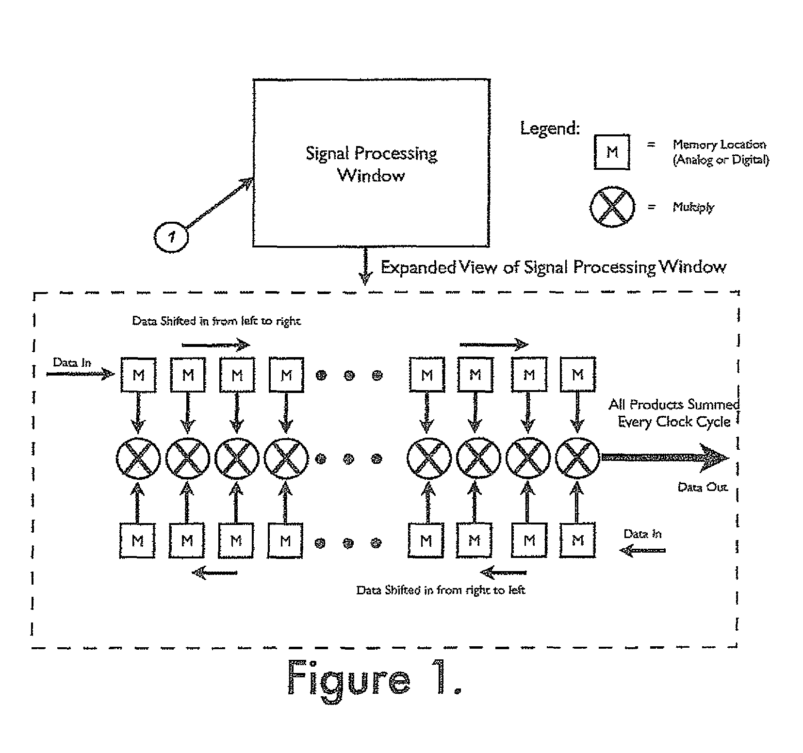
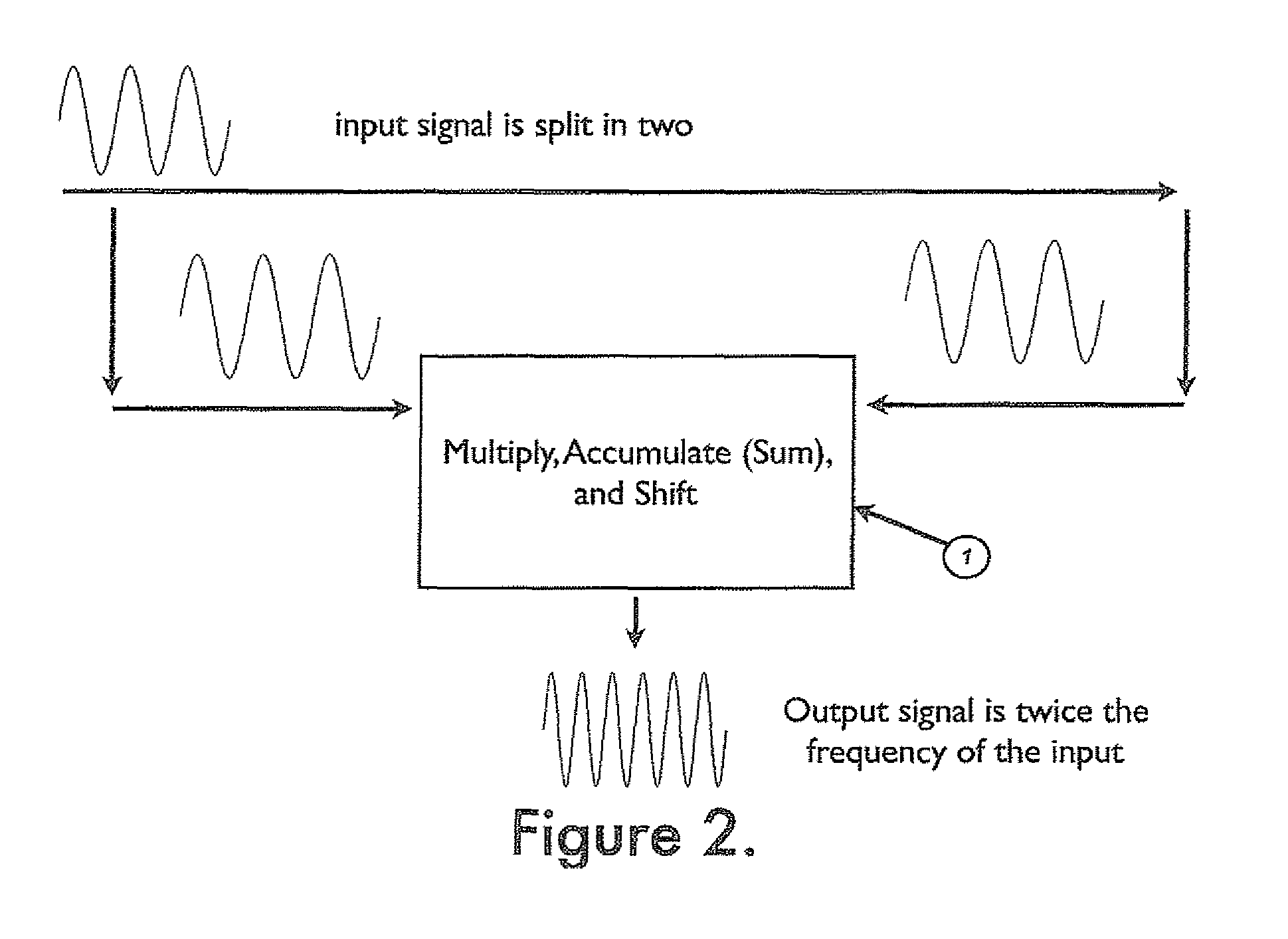
[0091]FIG. 1 shows the basic construction of the processing window. Referring to FIG. 2, a non-deterministic signal is split into two signal paths. The signal can be non-periodic or periodic, and does not have to be sinusoidal.

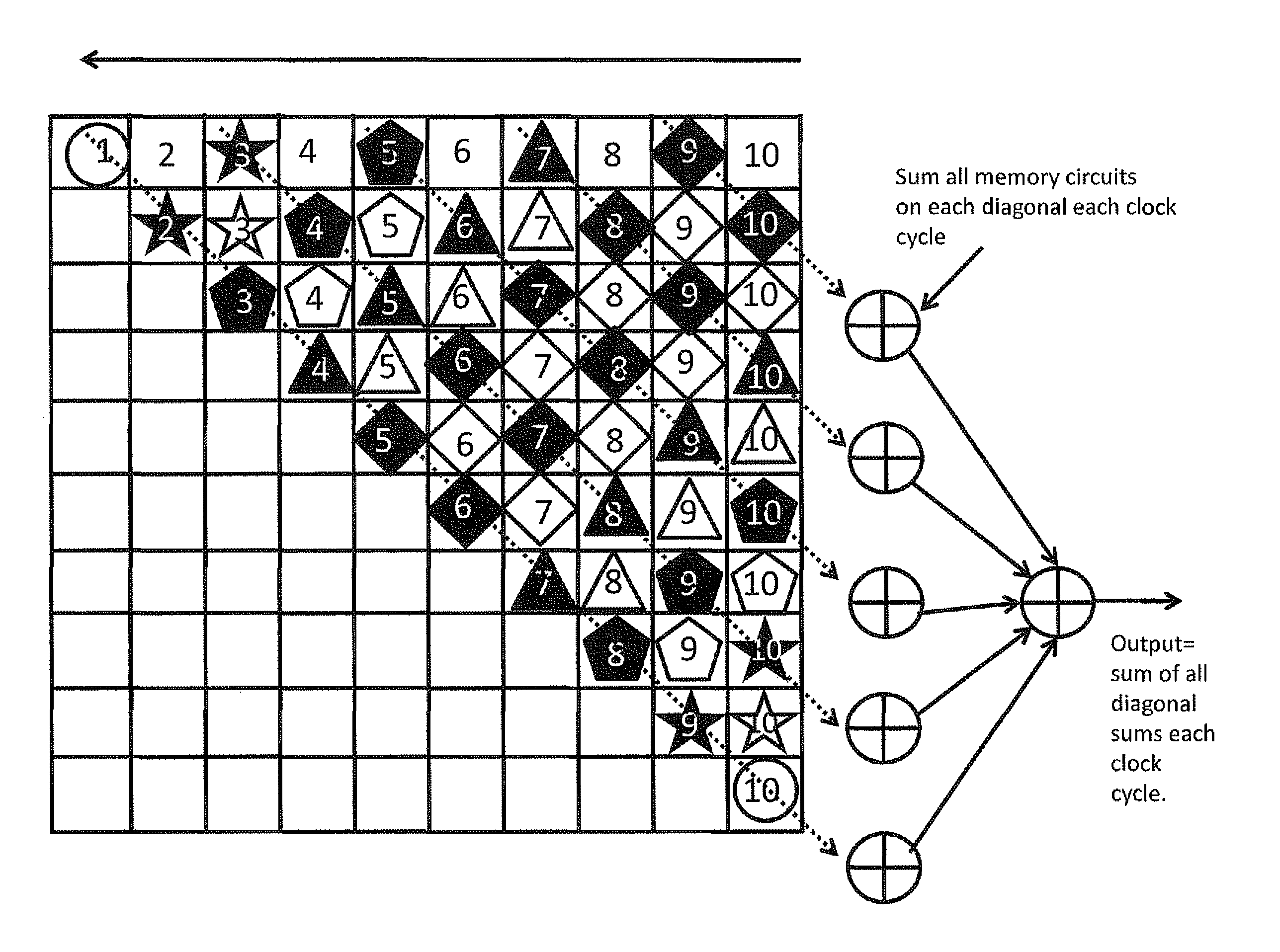
[0092]FIG. 2 shows a sinusoidal signal for ease of visualization. The signal is digitized and a multiply-sum window (item 1) is created with digital or analog memory locations. The amount of memory locations can be any value from 2 or greater. A window multiplies each corresponding data point of the two functions as they “pass” each other and then-sums them all together (as shown in FIG. 1). The most unique feature of this circuit is that both signals are moving. This is very close to classical convolution; however classical convolution requires that one signal be stationary. Each time the signals move to the next memory location, the multiplication and summation are repeated. Because the signals are derived from the same signal, their fundamental frequencies ...


PUM


Abstract

A method and system has been developed and demonstrated which provides real-time frequency translation, frequency compression, and user selectable response time for non-deterministic signals. This method and system provides for the real-time separation and isolation of theoretically an infinite amount of frequencies present in an incoming non-deterministic signal. The bandwidth of the filter for the separated frequencies is user selectable and provides varying rise times for the individual frequencies. The linear frequency shifting property of the algorithm creates bandwidth compression opportunities while signals are present in a channel for transmission.

Description

[0001]This application is a continuation-in-part of application Ser. No. 13 / 671,160, (the '160 application) filed Nov. 7, 2012. The '160 application is incorporated here by reference.BACKGROUND OF THE INVENTION[0002]Since the mid 70's music synthesizer companies have been attempting to adapt keyboard synthesizer technology to other non-keyboard (non mechanical switch activated) instruments such as guitars, brass, woodwinds, etc. The common techniques involved analog circuit processing which evaluated the frequency and amplitude of incoming musical notes, and then attempted to drive an electronic oscillator to duplicate these characteristics with user selectable parameters. These circuits and processes were pioneered by companies (some now defunct) such as Moog and ARP. However, the techniques were only moderately successful and always required modification to the instrument by way of attached, extraneous hardware. These techniques did not allow for reliable, successful processing by...

Claims


Application Information

Patent Timeline
Patent Type & Authority Patents(United States)
IPC IPC(8): G10L21/00G10L19/00G10L21/003G10H7/02
CPCG10L19/00G10H7/02G10L21/003G10H2250/571
Inventor LANNES, KENNETH JOHN
Owner LANNES KENNETH JOHN
Why Eureka
Try Eureka