Glow plug type acoustic resonance igniter

a technology of acoustic resonance and igniter, which is applied in the field of igniters, can solve the problems of multiple starts, damage or destruction of engines, and increase the cost of reconditioning engines for re-flight, so as to reduce or increase the oxygen/fuel

Active Publication Date: 2016-10-25
SIERRA SPACE CORP
View PDF16 Cites 24 Cited by
  • Summary
  • Abstract
  • Description
  • Claims
  • Application Information

AI Technical Summary

Benefits of technology

[0009]The primary hydrogen manifold and inlet port and the primary oxygen manifold and inlet port are arranged such that they have a high oxygen / fuel mixture ratio, for example 33, which is near the minimum energy for ignition of hydrogen and oxygen. The manifolds and the inlets are further arranged such that combustion in the primary combustion chamber drives the mixture ratio to a higher mixture ratio, for example 100, so that the combustion gases temperature reduce or eliminate the need for cooling of the primary combustion chamber. The highly oxygen rich combustion gases exit the primary combustion chamber through the exhaust orifice into the secondary combustion chamber where the temperature of the combustion gases is raised by the injection of additional hydrogen through the hydrogen manifold. The manifold forms an annulus around the secondary chamber and has inlet ports which are drilled at an angle, as shown in FIG. 1, so that the secondary hydrogen enters the combustion chamber through injection ports which are arranged to inject the hydrogen tangentially to the inside cylindrical wall of the secondary combustion chamber.

Problems solved by technology

Ignition is particularly a concern in liquid rocket engines where both the fuel and oxidizer are supplied as liquids to the chamber, because any momentary delay in ignition can result in the accumulation of an explosive mixture of fuel and oxidizer, resulting in a hard start which may damage or destroy the engine.
Reusable engines also require multiple starts, and, while replaceable pyrotechnic igniters are possible, they may leave residues which may add to the cost of reconditioning the engine for re-flight.
In such a case multiple starts become complicated.
Although engines utilizing hypergolic propellants readily perform multiple restarts and are widely used, using hypergolic propellant combinations limits propellant choice and can limit performance.
Moreover, generally hypergolic propellants are themselves expensive and toxic, such that the cost of procurement and handling may be significantly increased as compared to non-hypergolic propellants.
Hydrogen and oxygen are clean burning, require low ignition energy, and have wide flammability limits.
However, electrical ignition sources add complexity, require electrical power and a high-voltage electrical source, and are susceptible to electromagnetic damage such as caused by lightning strikes, and generally provide low ignition energy.

Method used


Image

  • Glow plug type acoustic resonance igniter
  • Glow plug type acoustic resonance igniter
  • Glow plug type acoustic resonance igniter

Examples


Embodiment Construction

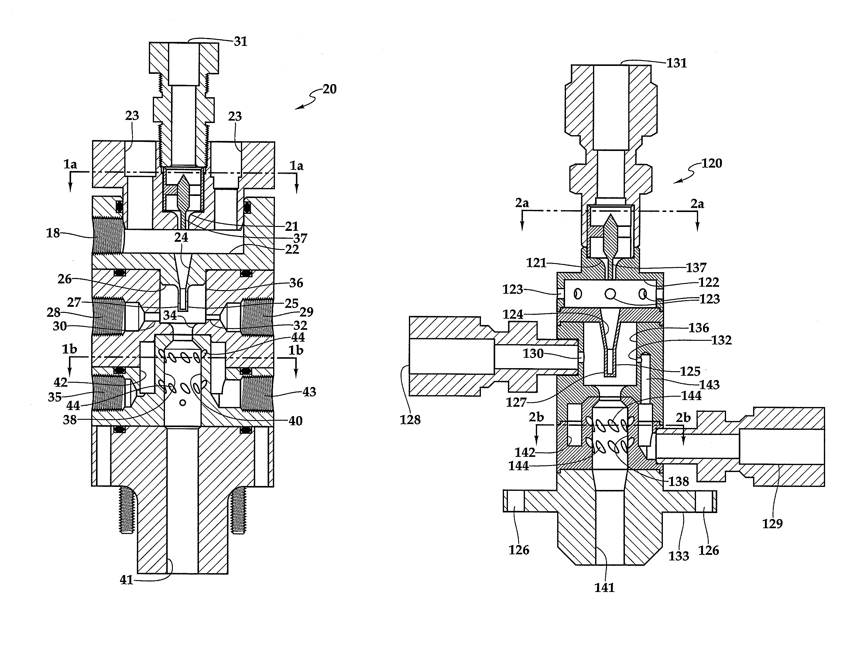
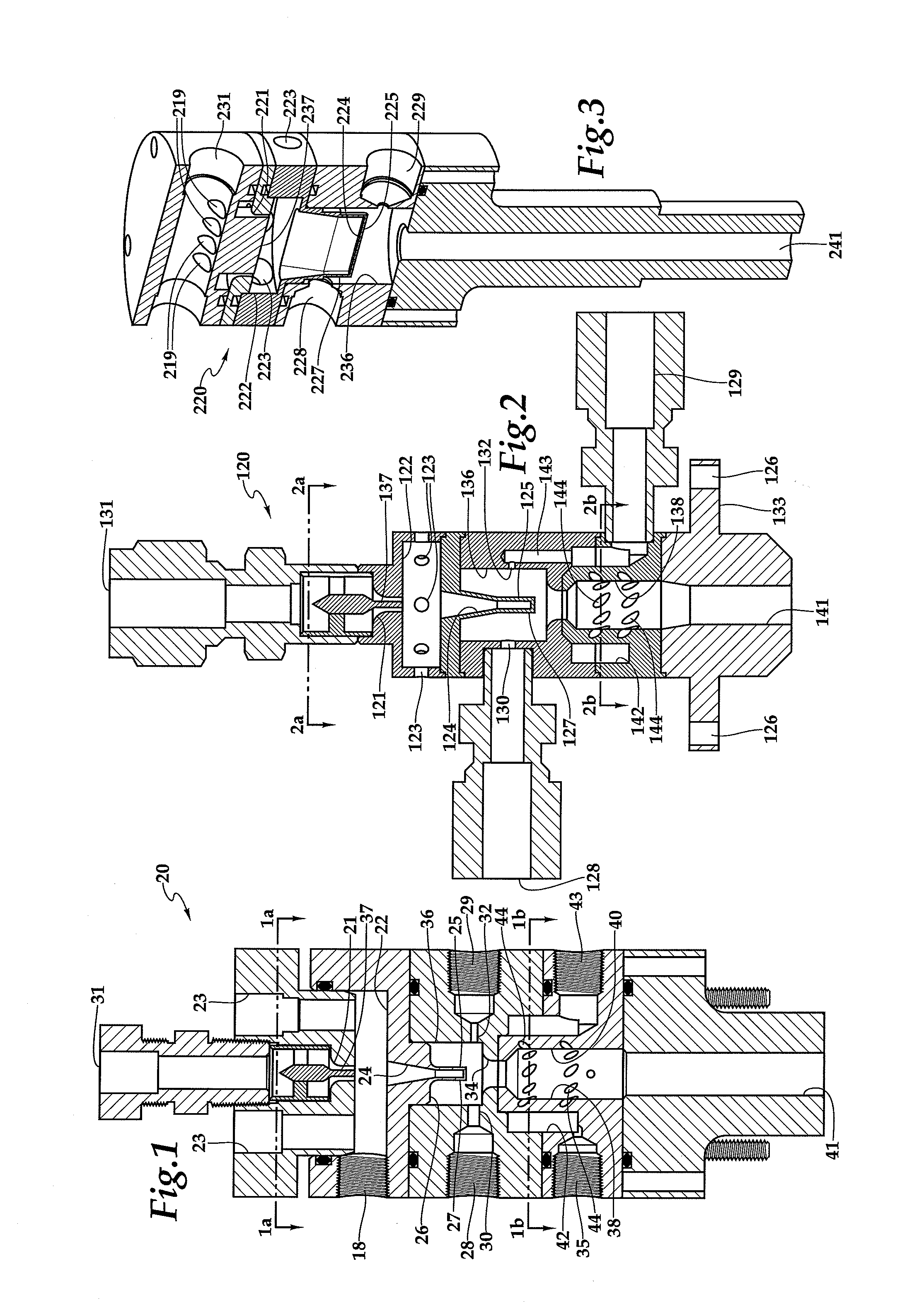
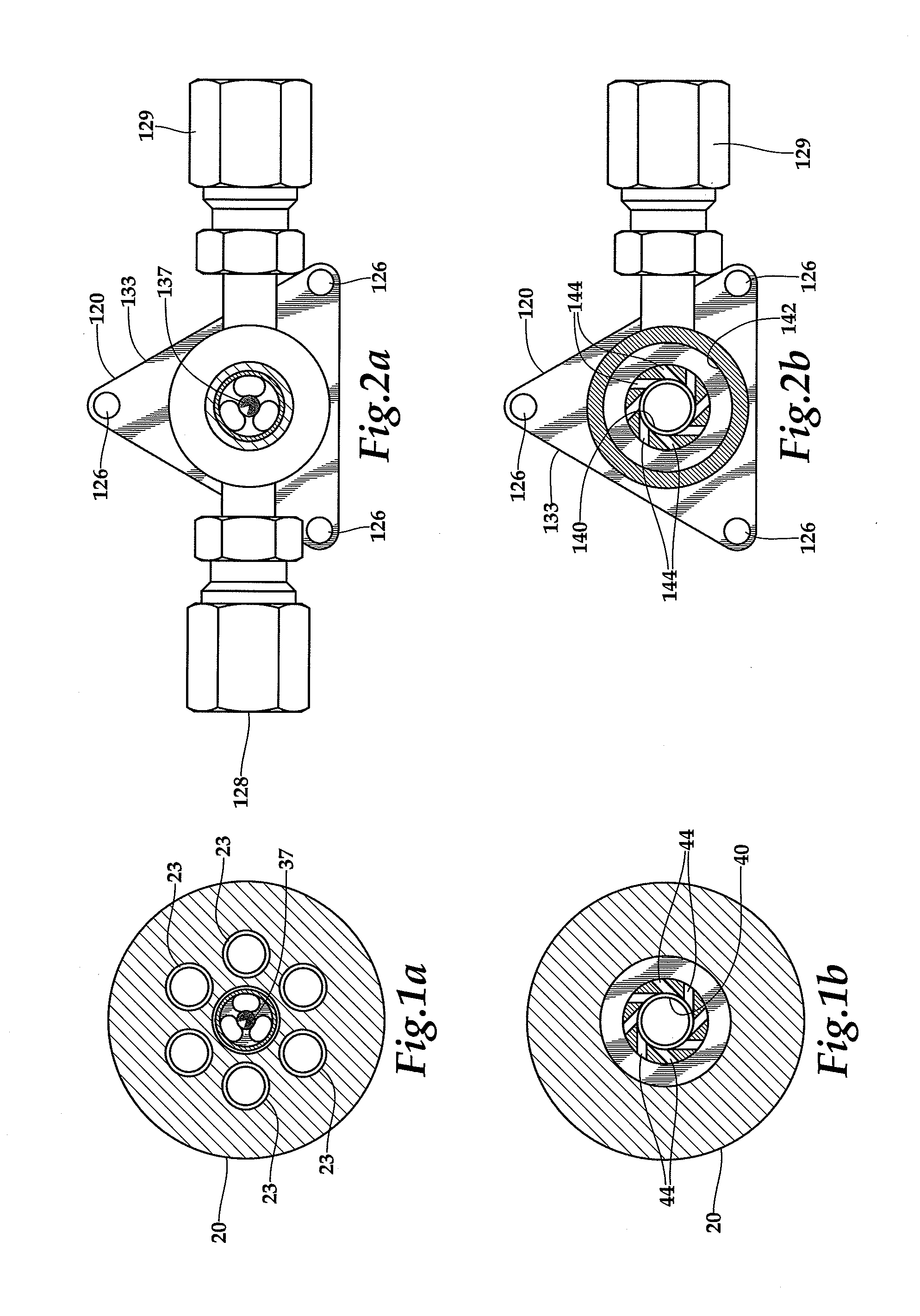
[0020]Referring more particularly to FIGS. 1-3, wherein like numbers refer to similar parts, a glow plug type acoustic resonance igniter 20 is shown in FIG. 1. The igniter 20 of FIG. 1 is a laboratory test article. A flight weight igniter 120 is shown in FIG. 2, and an alternative embodiment linear igniter 220 is shown in FIG. 3.

[0021]The resonance igniter 20 shown in FIG. 1 employs a high-pressure helium source 31, for example helium at 200-620 psia, which is accelerated through a sonic nozzle 21 into a lower pressure chamber 22 at, for example, 60 psia. A pintle 37 is mounted in the nozzle 21 to improve flow characteristics. A pressure test port 18 is shown in FIG. 1 for measuring pressure in the lower pressure chamber 22. The pressure in the lower pressure chamber 22 is maintained by outlets 23. The outlets form choked flow nozzles, whose outflows depend only upon the helium temperature and pressure but not on the external pressure to which the helium outlets 23 exhaust. Opposite...


PUM


Abstract

An acoustic resonance igniter uses high-pressure helium to heat a resonance cavity so a hot surface of the resonance cavity forms a source of ignition to a combustion chamber. The resonance cavity may be round or may extend linearly to increase the size of the hot surface. The combustion chamber is cooled by arranging a feed of hydrogen and oxygen which is oxygen rich and which becomes more so when ignition occurs. A second combustion chamber receives the combustion chamber output and adds additional hydrogen through ports tangential to the wall of the second combustion chamber to enrich the fuel ratio and cool the second combustion chamber. The acoustic resonance igniter is used to ignite a large rocket engine or to form a rocket thruster.

Description

CROSS REFERENCES TO RELATED APPLICATIONS[0001]This application claims priority on U.S. Provisional Patent App. No. 61 / 647,696 Filed May 16, 2012, the disclosure of which is incorporated by reference herein.STATEMENT AS TO RIGHTS TO INVENTIONS MADE UNDER FEDERALLY SPONSORED RESEARCH AND DEVELOPMENT[0002]This invention was made with government support under contract to US Air Force Research Laboratory # FA9300-10-C-2105. The government has certain rights in the invention. The government may exercise such rights over assignee's objection in accordance with 35 U.S.C. 202 and 203 if the government finds such action necessary in accord with 35 U.S.C. 203(a)(1-4).BACKGROUND OF THE INVENTION[0003]The present invention relates to igniters such as are used in rocket engines, jet engines and combustors in general; and to igniters utilizing a hot surface, heated by acoustically heated gas, as an ignition source in particular.[0004]Generally the safest, most reliable and most widely used method ...

Claims


Application Information

Patent Timeline
Patent Type & Authority Patents(United States)
IPC IPC(8): F02P23/00F02P3/12
CPCF02P23/00F02P3/12F02C7/264F02K9/62F02K9/18F02K9/766F02K9/42F02K9/76F02K9/72F02K9/78F02K9/64F02K9/95
Inventor MUNSON, SCOTT M.
Owner SIERRA SPACE CORP
Why Eureka
Try Eureka