RFID torque sensing tag system for fasteners

a technology of torque sensing and fastener, which is applied in the direction of screws, instruments, force/torque/work measurement apparatus, etc., can solve the problems of improper tightening, tensile fracture, galling, etc., and achieves high reliability data, cost-effectiveness, and improved safety.

Active Publication Date: 2016-11-01
NASA
View PDF30 Cites 49 Cited by
  • Summary
  • Abstract
  • Description
  • Claims
  • Application Information

AI Technical Summary

Benefits of technology

[0041]An additional object of the present invention is to provide a RFID torque-sensing tag system for fasteners that provides for remote reading which eliminates manual checking of each fastener.
[0042]Yet another possible object of the invention is to provide RFID torque-sensing tag system for fasteners that provides highly reliable data and cost effective means to observe operational status of equipment and other systems.
[0043]A further object of the present invention is to provide a RFID torque-sensing tag system for fasteners that improves safety by reducing quality control labor and providing a cost effective means to detect loose fasteners to prevent injury to people and damage to critical equipment.

Problems solved by technology

The need for improved fastener tension sensing systems is driven by costly documented failures in a wide range of application and for many different causes.
Fastener failure analysis has shown that the causes include, but are not limited to, improper tightening, fatigue, tensile fracture, galling, insufficient preload, thread stripping, creep, stress relaxation, and self-loosening.
Such disasters include bridges, tunnels, and train rails where fastener failures are known to have caused disastrous results.
Automotive failures occur due to common problems such as lug bolt failures in automotive racing.
Aircraft are some of the most intensely inspected products in existence but entire fleets have been grounded due to loose bolts in certain subassemblies.
Theme park accidents have been caused by fastener failures.
However, the prior art does not teach such a system.
Verifying that multiple fasteners are properly torqued, compressed, or otherwise secured to the desired tension to apply the required force is typically a labor intensive and / or expensive proposition.
However, prior art fastener torque sensors tend to be expensive, complicated, and / or require modification of the fasteners.
Such a system is likely to be cost prohibitive for most applications.
Integration of an RFID circuit with a bolt typically implies that the embedded RFID circuit will have a very small antenna and hence will be very range limited.
However, the prior art does not provide a way to utilize RFID technology for a low priced torque sensor that utilizes standard fasteners.
The following prior art patents and applications disclose various types of torque sensing systems, but do not address the problems discussed hereinbefore:
As seen from above, the prior art does not teach how to provide a low cost torque monitoring system using strictly or pseudo passive wireless tags that operates with standard off the shelf or unmodified fasteners.
Moreover, even the above discussed art that utilize RFIDs require relatively expensive modified bolts that have a very limited range of transmission so that the fastener torque sensing systems are not only expensive but have significantly limited functionality.

Method used


Image

  • RFID torque sensing tag system for fasteners
  • RFID torque sensing tag system for fasteners
  • RFID torque sensing tag system for fasteners

Examples


Embodiment Construction

[0079]Detailed descriptions of the preferred embodiment are provided herein. It is to be understood, however, that the present invention may be embodied in various forms. Therefore, specific details disclosed herein are not to be interpreted as limiting, but rather as a basis for the claims and as a representative basis for teaching one skilled in the art to employ the present invention in virtually any appropriately detailed system, structure or manner. It will be understood that the components can sometimes be shown herein in substantially conceptual form for ease of understanding. The illustrations are not intended to represent manufacturing level drawings with manufacturing level dimension precision, sizes, or details.

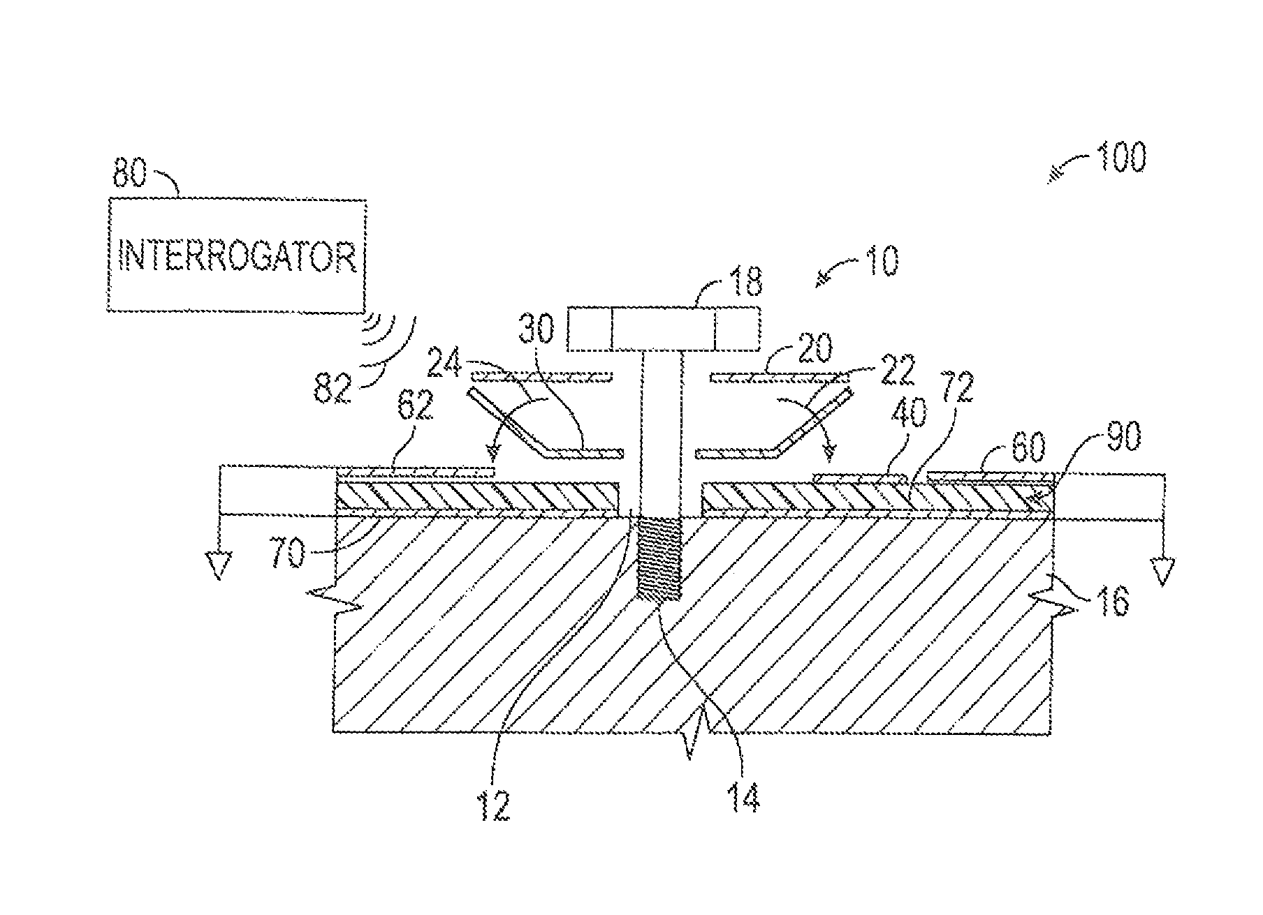
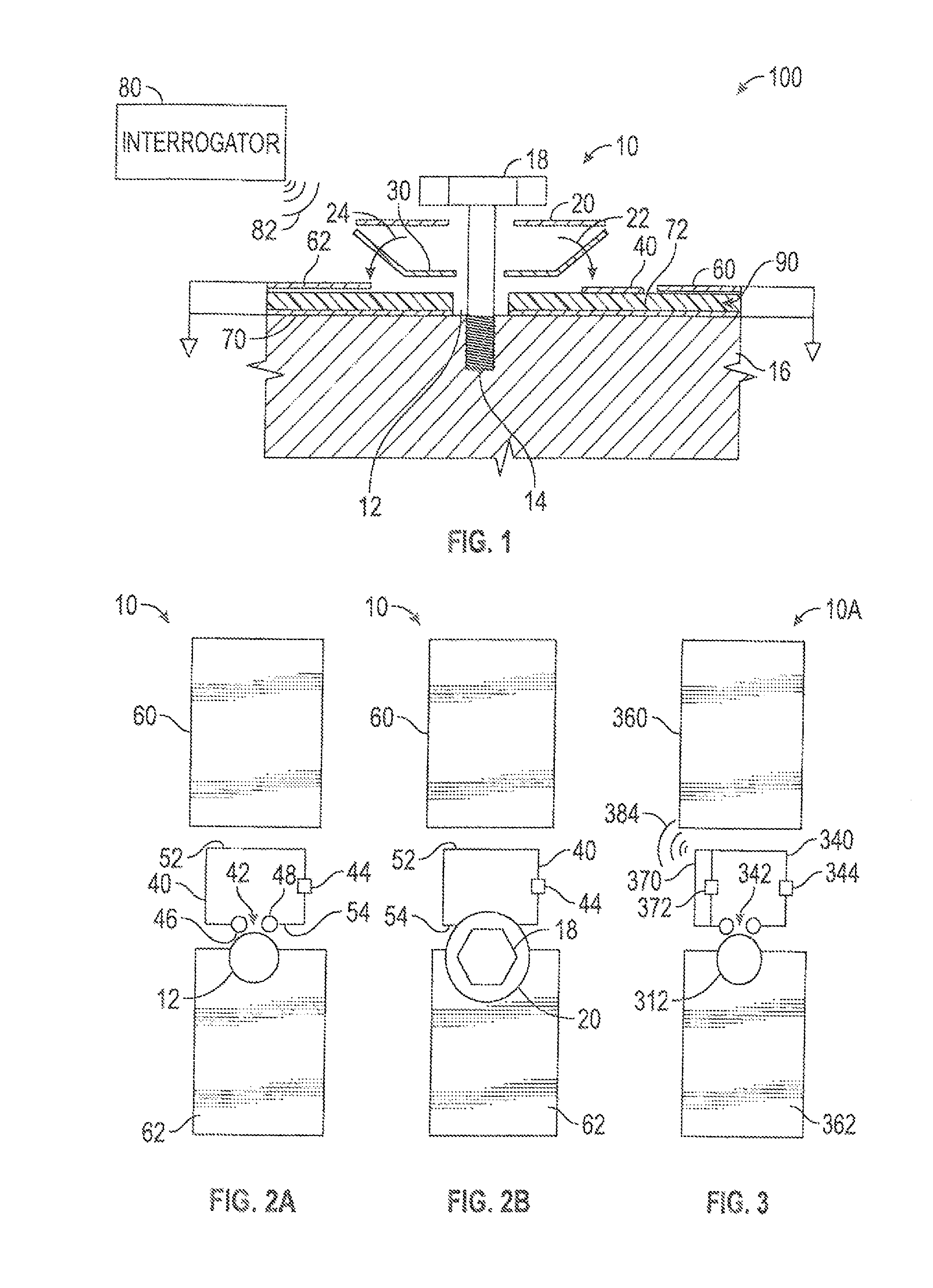
[0080]Referring now to the drawings and, more specifically to FIG. 1, there is shown for illustrational purposes an elevational cross-sectional diagrammatic view of one possible embodiment of RFID torque sensing tag system 100. RFID tag 10 (sometimes referred to as...


PUM

PropertyMeasurementUnit
excitation frequencyaaaaaaaaaa
transmission distanceaaaaaaaaaa
distanceaaaaaaaaaa

Abstract

The present invention provides an RFID-based torque sensor that can be used to quickly monitor off the shelf fasteners including fasteners that are used in expensive satellites or other uses where fastener failure can be very costly. In one embodiment, an antenna, RFID ring and spring comprise a sensor tag that can be interrogated with an interrogation signal produced by an interrogator device. When sufficient torque is applied to the fastener, an RFID circuit is connected, and produces a radio frequency (RF) signal that can be read by the interrogator. In one embodiment, the RFID circuit does not transmit when the spring member is not compressed, thereby indicating insufficient tensioning of the fastener. The present invention offers the ability to remotely, quickly, and inexpensively verify that any number of fasteners are torqued properly upon initial installation. Where applicable, the present invention allows low cost monitoring over the life of the fastener.

Description

STATEMENT OF GOVERNMENT INTEREST[0001]The invention described herein was made in the performance of work under a NASA contract and is subject to the provisions of Section 305 of the National Aeronautics and Space Act of 1958, now codified in 51 U.S.C. 20135.CROSS REFERENCE TO OTHER PATENT APPLICATIONS[0002]None.BACKGROUND OF THE INVENTION[0003]1. Field of the Invention[0004]The present invention relates generally to fastener tension sensing systems and more specifically to a RFID torque sensing tag system for fasteners.[0005]2. Background of the Invention[0006]Fasteners such as bolts, nuts, studs, washers, rivets, and the like are used in innumerable structures and machines. The need for improved fastener tension sensing systems is driven by costly documented failures in a wide range of application and for many different causes. Fastener failure analysis has shown that the causes include, but are not limited to, improper tightening, fatigue, tensile fracture, galling, insufficient p...

Claims


Application Information

Patent Timeline
Patent Type & Authority Patents(United States)
IPC IPC(8): G06K7/10F16B31/02G01L5/24
CPCG06K7/10366F16B31/028G01L5/243
Inventor FINK, PATRICK W.LIN, GREGORY Y.NGO, PHONG H.KENNEDY, TIMOTHY F.
Owner NASA
Why Eureka
Try Eureka