Reducing agent supplying device

Active Publication Date: 2016-11-08
DENSO CORP
View PDF10 Cites 0 Cited by
  • Summary
  • Abstract
  • Description
  • Claims
  • Application Information

AI Technical Summary

Benefits of technology

[0011]As described above, according the aspect of the present disclosure, the NOx purification rate may be improved. Furthermore, even when the exhaust pre

Problems solved by technology

Therefore, when a pressure in the exhaust passage (i.e., an exhaust pressure) is high so that supply of the reducing agent into the exhaust passage is not possible, the sw

Method used


Image

  • Reducing agent supplying device
  • Reducing agent supplying device
  • Reducing agent supplying device

Examples


Embodiment Construction

[0019]A plurality of embodiments of the present disclosure will be described hereinafter referring to drawings. In the embodiments, a part that corresponds to a matter described in a preceding embodiment may be assigned with the same reference numeral, and redundant explanation for the part may be omitted. When only a part of a configuration is described in an embodiment, another preceding embodiment may be applied to the other parts of the configuration. The parts may be combined even if it is not explicitly described that the parts can be combined. The embodiments may be partially combined even if it is not explicitly described that the embodiments can be combined, provided there is no harm in the combination.

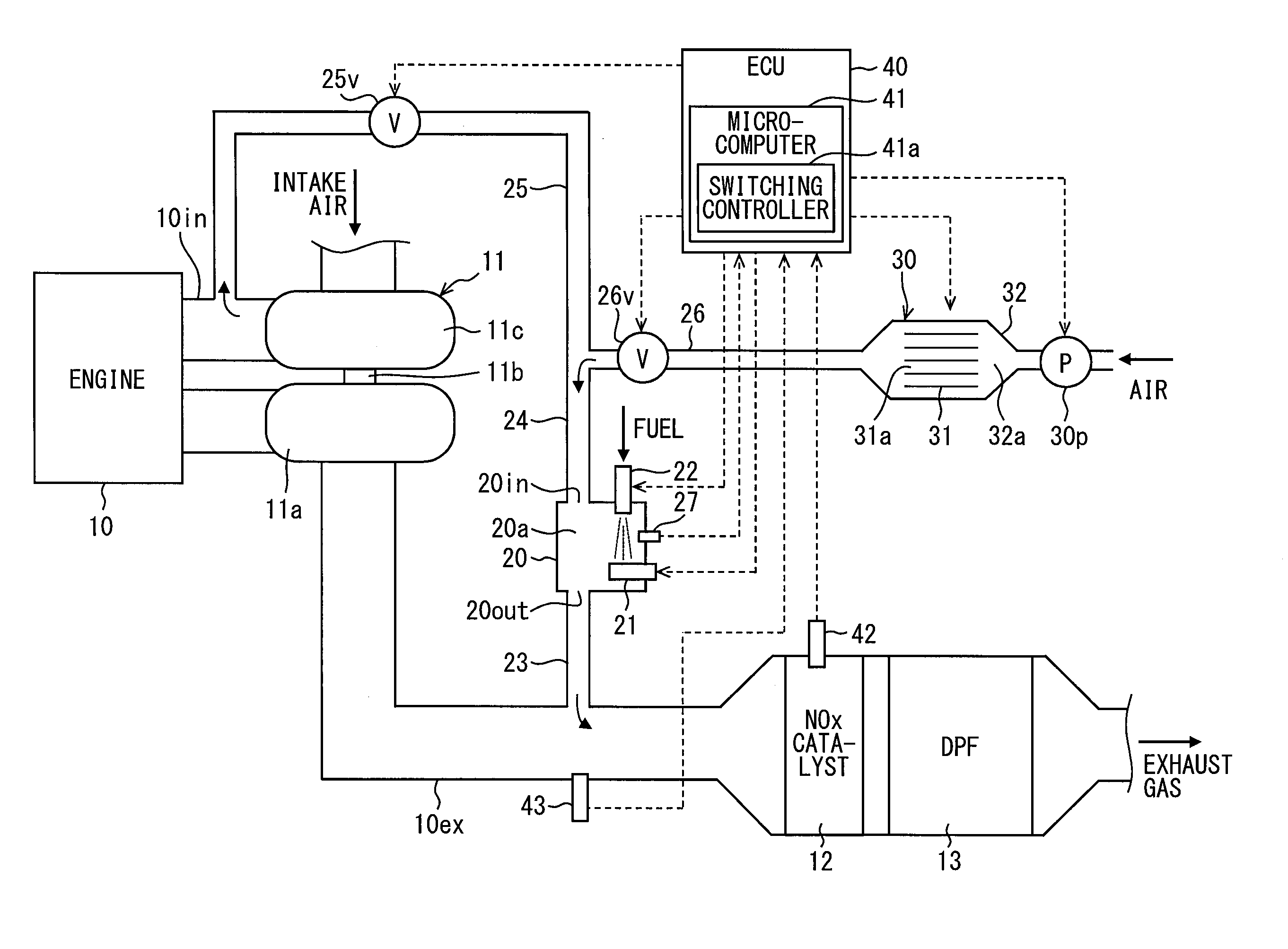
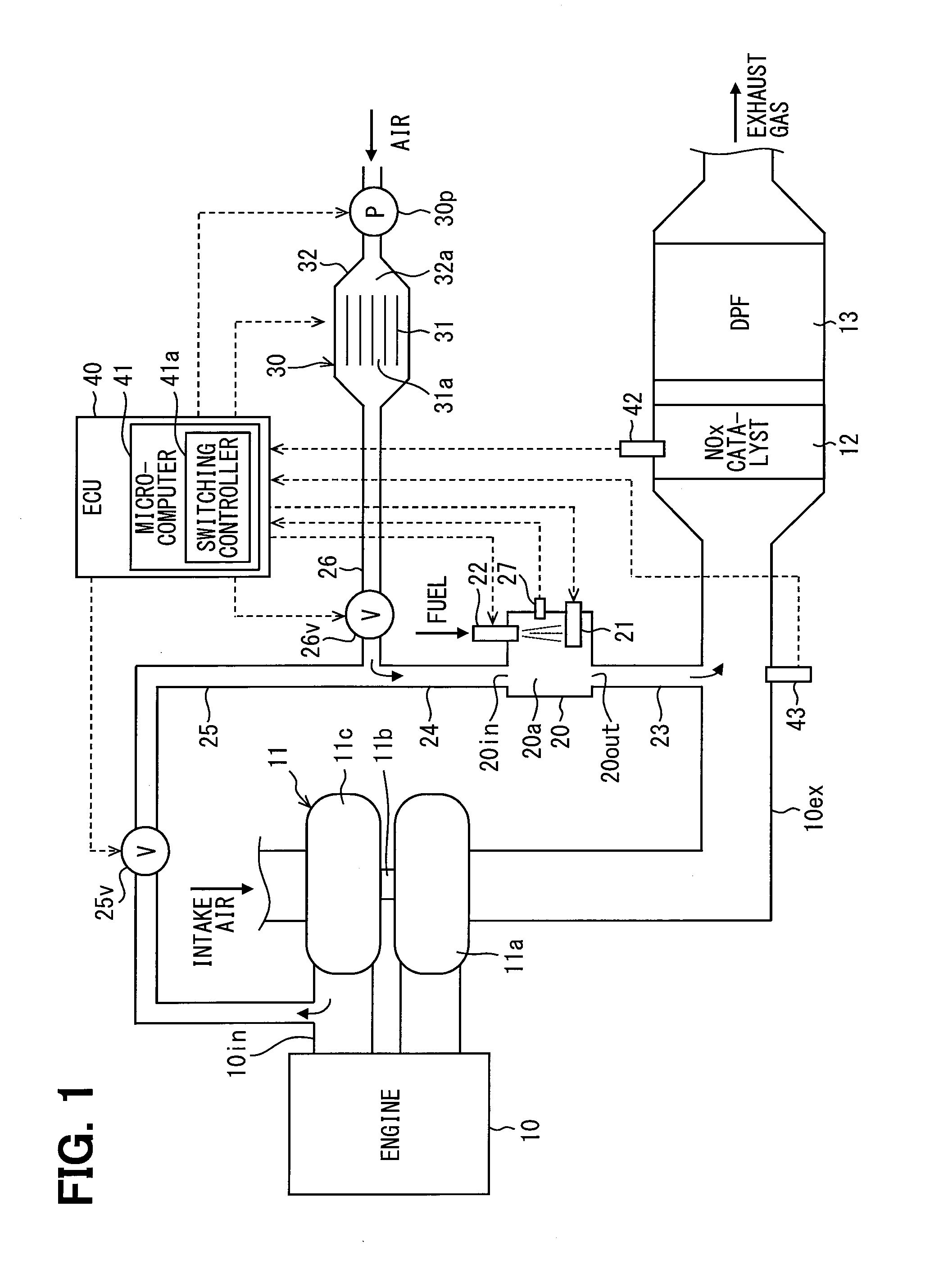
[0020]A combustion system as illustrated in FIG. 1 includes an internal combustion engine 10, a supercharger 11, a NOx purifying device 12, a diesel particulate filter (DPF 13), and a reducing agent supplying device. The combustion system is mounted on a vehicle and the vehic...


PUM

PropertyMeasurementUnit
Temperatureaaaaaaaaaa
Pressureaaaaaaaaaa

Abstract

A reducing agent supplying device includes a reaction container, an ozone generator, an air pump, an ozone-containing air pipe, a compressed air pipe, a switching device, and a switching controller. The reaction container defines a reaction chamber therein in which a reducing agent is reformed. The ozone generator generates ozone from oxygen in air. The air pump supplies air into the ozone generator. An ozone-containing air flows through the ozone-containing air pipe toward the reaction chamber. A portion of a compressed air flows through the compressed air pipe toward the reaction chamber. The switching device switches between an air pump mode, in which the ozone-containing air is supplied into the reaction chamber, and a supercharging mode, in which the compressed air is supplied into the reaction chamber. The switching controller controls the switching device based on a catalyst temperature, which is a temperature of the reducing catalyst, and an exhaust pressure, which is a pressure in the exhaust passage.

Description

CROSS REFERENCE TO RELATED APPLICATION[0001]This application is based on and incorporates herein by reference Japanese Patent Application No. 2014-190155 filed on Sep. 18, 2014.TECHNICAL FIELD[0002]The present disclosure relates to a reducing agent supplying device for supplying a reducing agent used for NOx reduction into an exhaust passage at a position upstream of a reducing catalyst.BACKGROUND[0003]A patent literature 1 (JP 2000-54833 A) disclosed a reducing agent supplying device that includes an ozone generator for generating an ozone, an air pump for blowing an air containing the ozone generated by the ozone generator, a fuel injector for injecting a fuel as a reducing agent, and a heater. A mixed air of the blown air and the injected fuel is heated by the heater, whereby the fuel is oxidized with oxygen in air, i.e., the fuel is reformed. The reformed fuel is supplied into an exhaust passage at a position upstream of a NOx catalyst to reduce NOx in the existence of the NOx c...

Claims


Application Information

Patent Timeline
IPC IPC(8): F01N3/00F01N3/08F01N3/20B01D53/94F01N3/30F01N3/10F01N5/04F01N3/32F02B37/16F01N13/00
CPCF01N3/0842B01D53/9431B01D53/9495F01N3/0814F01N3/0871F01N3/2066F01N3/303F01N3/32B01D2251/104F01N13/0097F01N2240/16F01N2240/30F01N2240/38F01N2260/26F01N2560/06F01N2560/08F01N2570/14F01N2610/03F01N2610/08F01N2610/085F01N2900/1406F01N2900/1602F02B37/164Y02T10/12
Inventor YAHATA, SHIGETOKINUGAWA, MASUMITARUSAWA, YUUKIHOSODA, MAOMAJIMA, YUSUKE
Owner DENSO CORP
Why Eureka
Try Eureka