Thermoelectric conversion apparatus

a technology of thermoelectric conversion apparatus and thermoelectric converter, which is applied in the manufacture/treatment of thermoelectric devices, electrical apparatus, thermoelectric devices, etc., can solve the problems of difficult for a thermoelectric conversion apparatus to adopt a flexible structure, curved surfaces of heat sources, and inconvenient use, so as to reduce the risk of breakage upon bending, reduce the risk of bending, and the effect of efficient stress absorption

Active Publication Date: 2016-11-15
NEC CORP +1
View PDF23 Cites 1 Cited by
  • Summary
  • Abstract
  • Description
  • Claims
  • Application Information

AI Technical Summary

Benefits of technology

[0011]It is, therefore, an object of the present invention to provide a flexible thermoelectric conversion apparatus having high reliability.
[0012]Another object of the present invention is to provide a method of manufacturing such a thermoelectric conversion apparatus.

Problems solved by technology

However, most of heat sources have curved surfaces or irregularities.
However, a thermoelectric conversion apparatus generally has a complicated structure in which a large number of thermocouples having a p-n junction are arranged and connected to each other.
Therefore, it has been difficult for a thermoelectric conversion apparatus to adopt a flexible structure in view of the reliability and the like.
Nevertheless, if even one junction or wire is broken in a structure having a large number of thermocouples being connected, the function of thermoelectric power generation is impaired.
Accordingly, there are still problems in a highly reliable operation of a flexible device.
As a result, the thermoelectric conversion function may be impaired by breakage of the magnetic film or the electrode, separation of the junction portion of the magnetic film and the electrode, and the like.
If the magnetic film or the electrode should be broken, such a high stress is applied directly to the magnetic film and the electrode, resulting in a large scattering loss of spin currents, for example, in a junction of the magnetic body and the electrode.

Method used


Image

  • Thermoelectric conversion apparatus
  • Thermoelectric conversion apparatus
  • Thermoelectric conversion apparatus

Examples


first embodiment

Configuration

[0048]Next, a first embodiment of the present invention will be described with reference to the drawings.

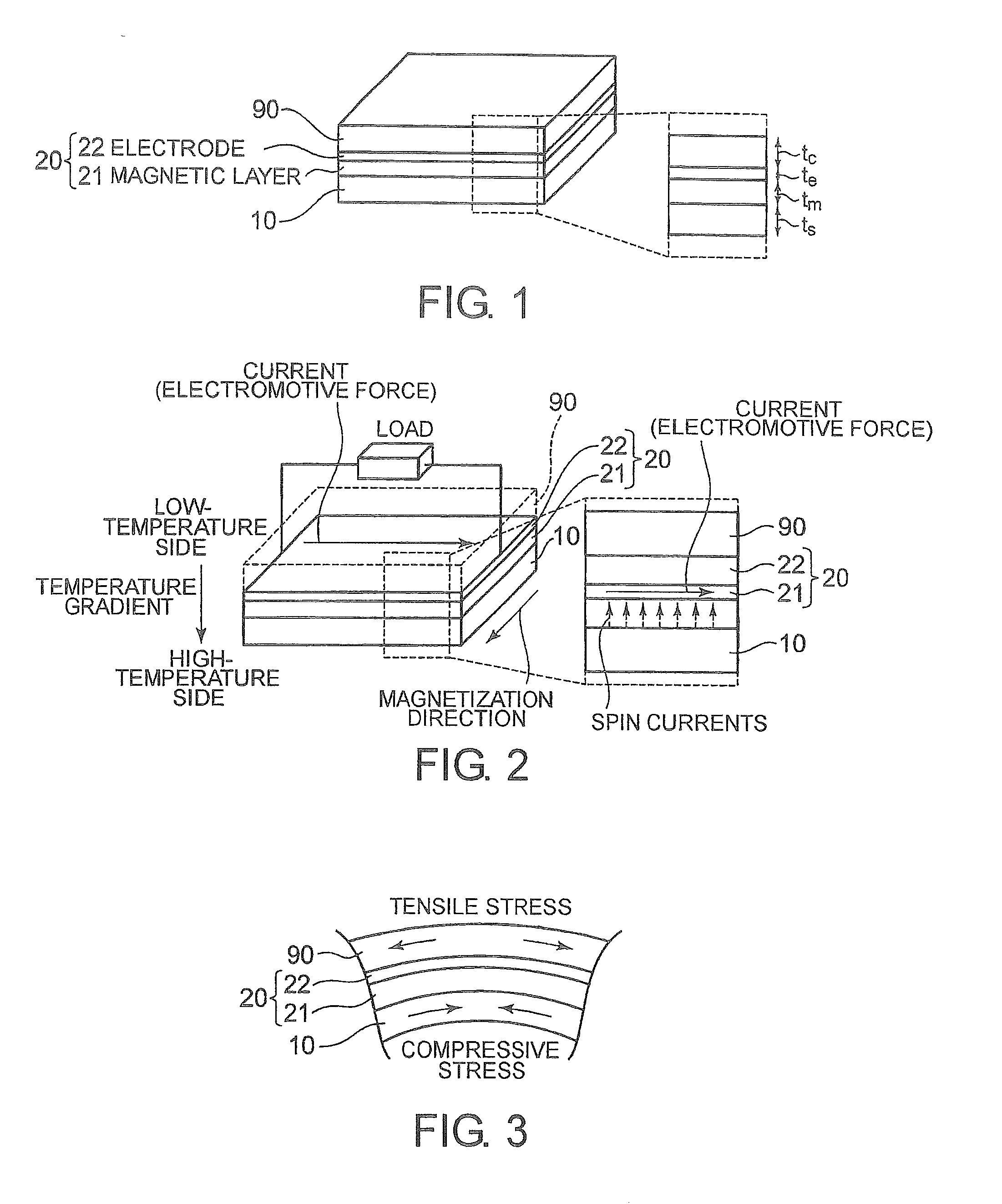
[0049]Referring to FIG. 1, which is a perspective view showing a thermoelectric conversion apparatus according to a first embodiment of the present invention, the thermoelectric conversion apparatus has a multilayer structure including a substrate 10 having flexibility, a power generation part 20 including a magnetic layer 21 and an electrode layer 22, and a cover layer 90.

[0050]A flexible substrate of an organic resin or the like is used as the substrate 10. A thermoplastic material such as polyolefin or vinyl resin may be used in a case where no intense heat is applied upon production of the device or in applications of thermoelectric conversion at low temperatures. However, in a case of using a process that requires heating, for example, upon deposition of the magnetic layer or the electrode or in applications of thermoelectric conversion at high temperatures of 1...

example 1

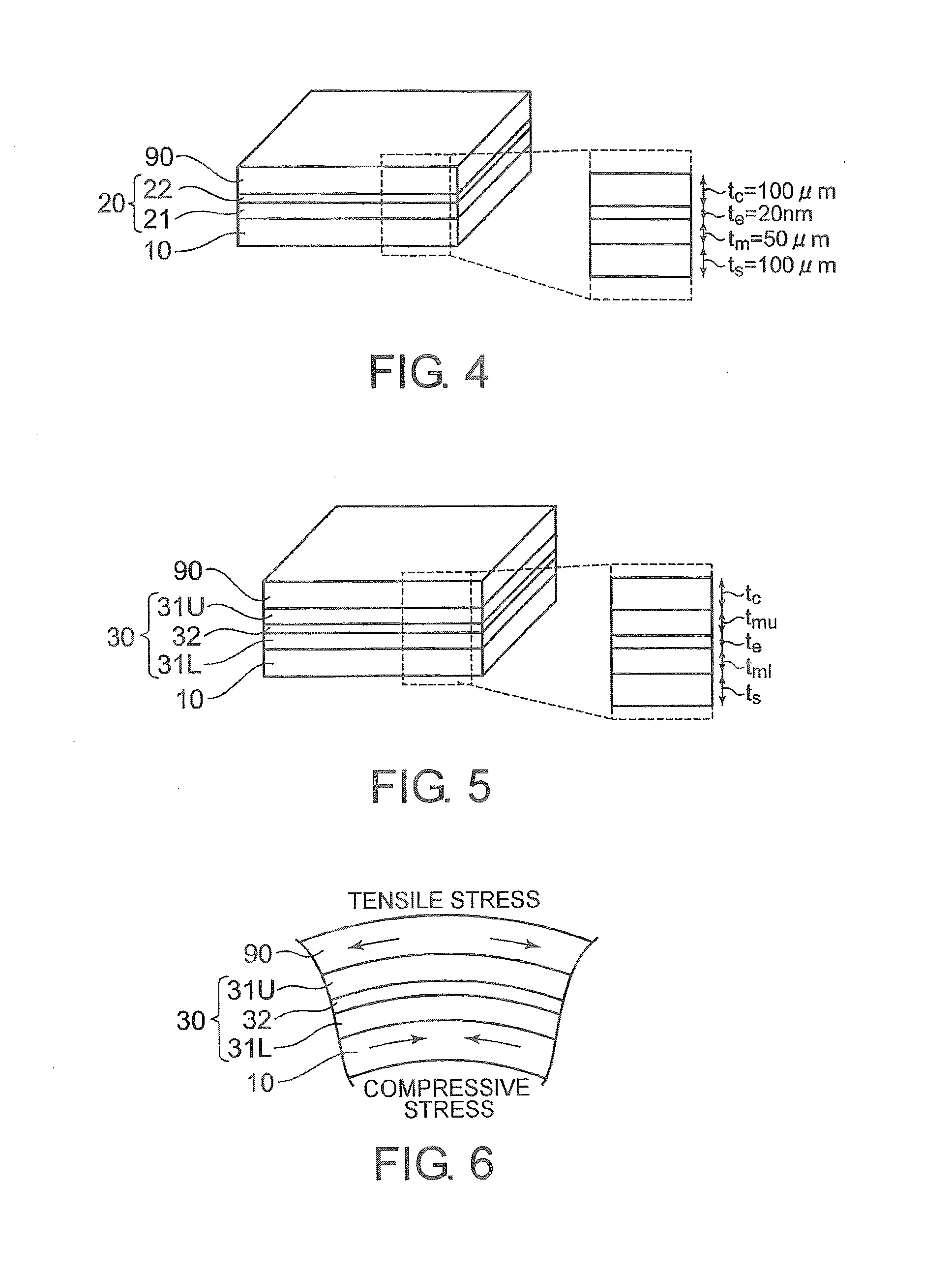
[0064]Referring to FIG. 4, in a thermoelectric conversion apparatus according to Example 1 of the present invention, a yttrium iron garnet (with composition of BiY2Fe5O12; hereinafter referred to as Bi:YIG) film in which Bi has been substituted for part of Y sites is used as the magnetic layer 21. Pt is used as the electrode layer 22. Here, the thickness of the magnetic layer 21 (Bi:YIG film) is set such that tm=50 μm, and the thickness of the electrode layer 22 (Pt electrode) is set such that te=20 nm. A polyimide substrate is used as the flexible substrate 10, and an acrylic resin is used as the cover layer 90. The thicknesses of the flexible substrate 10 and the cover layer 90 are set such that ts=tc=100 μm.

[0065]The magnetic layer 21, which is formed of Bi:YIG is deposited by an AD method. As a Bi:YIG material, Bi:YIG particulates having a diameter of 300 nm are used. Those Bi:YIG particulates are packed into an aerosol generation container, and the polyimide substrate 10 is fix...

second embodiment

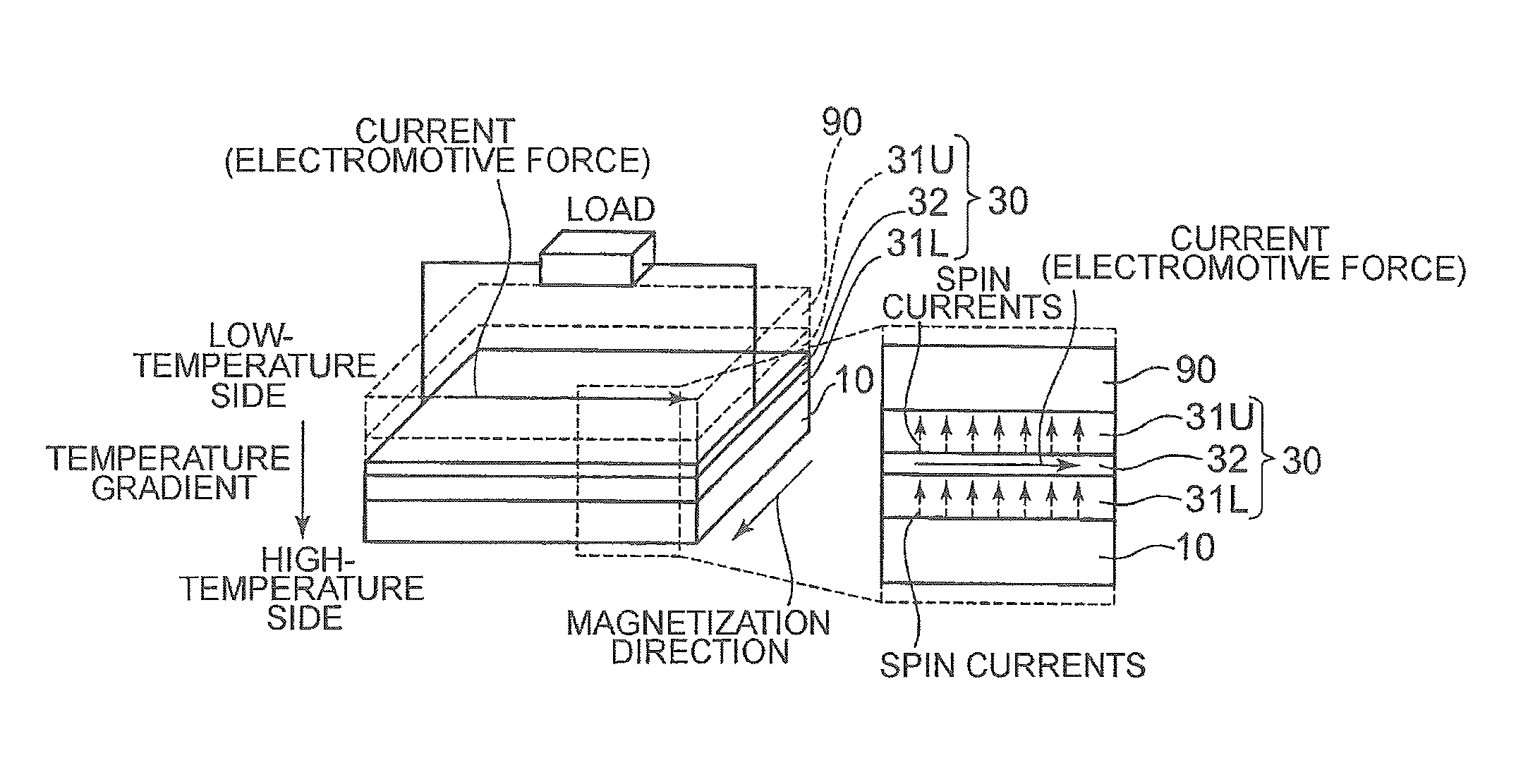
[0068]Referring to FIG. 5, which shows a thermoelectric conversion apparatus according to a second embodiment of the present invention, the thermoelectric conversion apparatus includes magnetic layers of a first magnetic layer (lower magnetic layer) 31L formed on one layer surface of the electrode layer 32 and a second magnetic layer (upper magnetic layer) 31U formed on the other layer surface of the electrode layer 32.

[0069]The magnetic body, the electrode layer 32, the flexible substrate 10, the cover layer 90, and the like may employ the same materials as used in the first embodiment. As with the first embodiment, the thickness tc of the cover layer 90 is designed to be nearly equal to the thickness ts of the flexible substrate 10.

[0070]Specifically, the second embodiment differs from the first embodiment in that the power generation part 30 is formed by a multilayer structure of the upper magnetic layer 31U, the electrode layer 32, and the lower magnetic layer 31L. At that time,...


PUM


Abstract

A thermoelectric conversion apparatus has a substrate and a power generation part. The power generation part has a magnetic layer with magnetization and an electrode layer made of a material exhibiting a spin-orbit interaction and formed on the magnetic layer. The substrate and the power generation part have flexibility. This thermoelectric conversion apparatus further has a cover layer having flexibility and formed on the substrate so as to cover at least the power generation part.

Description

TECHNICAL FIELD[0001]The present invention relates to an apparatus for converting thermal energy into electric energy.BACKGROUND ART[0002]While efforts have actively been made toward environmental issues and energy issues, expectations of thermoelectric conversion technology have grown under such circumstances. Because heat is the most common energy source that is available from various situations, such as body heat, solar heat, engines, and industrial exhaust heat, thermoelectric conversion is expected to become more important in future for efficiency enhancement in energy use for a low-carbon economy or for applications of power supply to ubiquitous terminals, sensors, or the like.[0003]A wide variety of heat sources, such as body heat of humans or animals, lighting (fluorescent lamps and street lamps), IT equipment (display server), automobiles (peripheral area of engine and exhaust pipe), public facilities (waste incinerators and water service pipes), buildings (walls, windows, ...

Claims


Application Information

Patent Timeline
Patent Type & Authority Patents(United States)
IPC IPC(8): H01L35/30H01L35/02H01L43/02H01L37/00H01L35/34H01L21/00
CPCH01L35/02H01L35/34H01L37/00H01L43/02H10N10/80H10N15/00H10N10/01H10N10/17H10N50/80
Inventor KIRIHARA, AKIHIROENDOH, HIROYUKIMANAKO, TAKASHIUCHIDA, KENICHISAITOH, EIJI
Owner NEC CORP
Why Eureka
Try Eureka