
Systems and methods for clock alignment using pipeline stages

a technology of pipeline stages and clocks, applied in the direction of digital transmission, pulse automatic control, generating/distributing signals, etc., can solve the problems of increasing the loss of the useful portion of the clock cycle, exacerbate the uncertainty between related clock signals, and limited clock generation options of field-programmable gate arrays (fpgas)

Active Publication Date: 2016-11-22
ALTERA CORP
View PDF4 Cites 3 Cited by
  • Summary
  • Abstract
  • Description
  • Claims
  • Application Information

AI Technical Summary

Benefits of technology

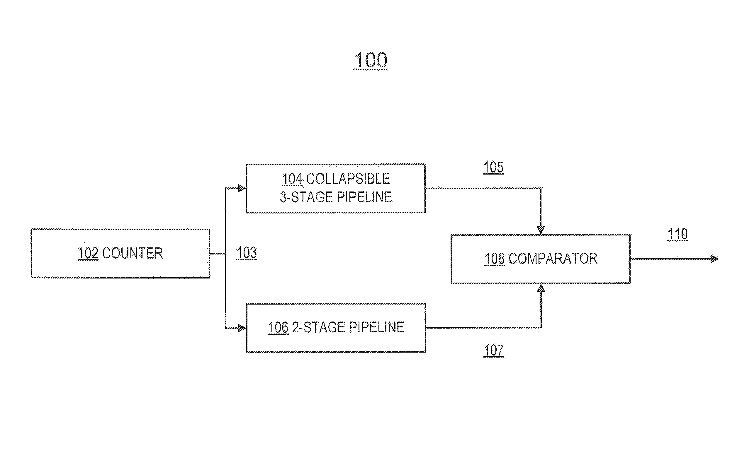
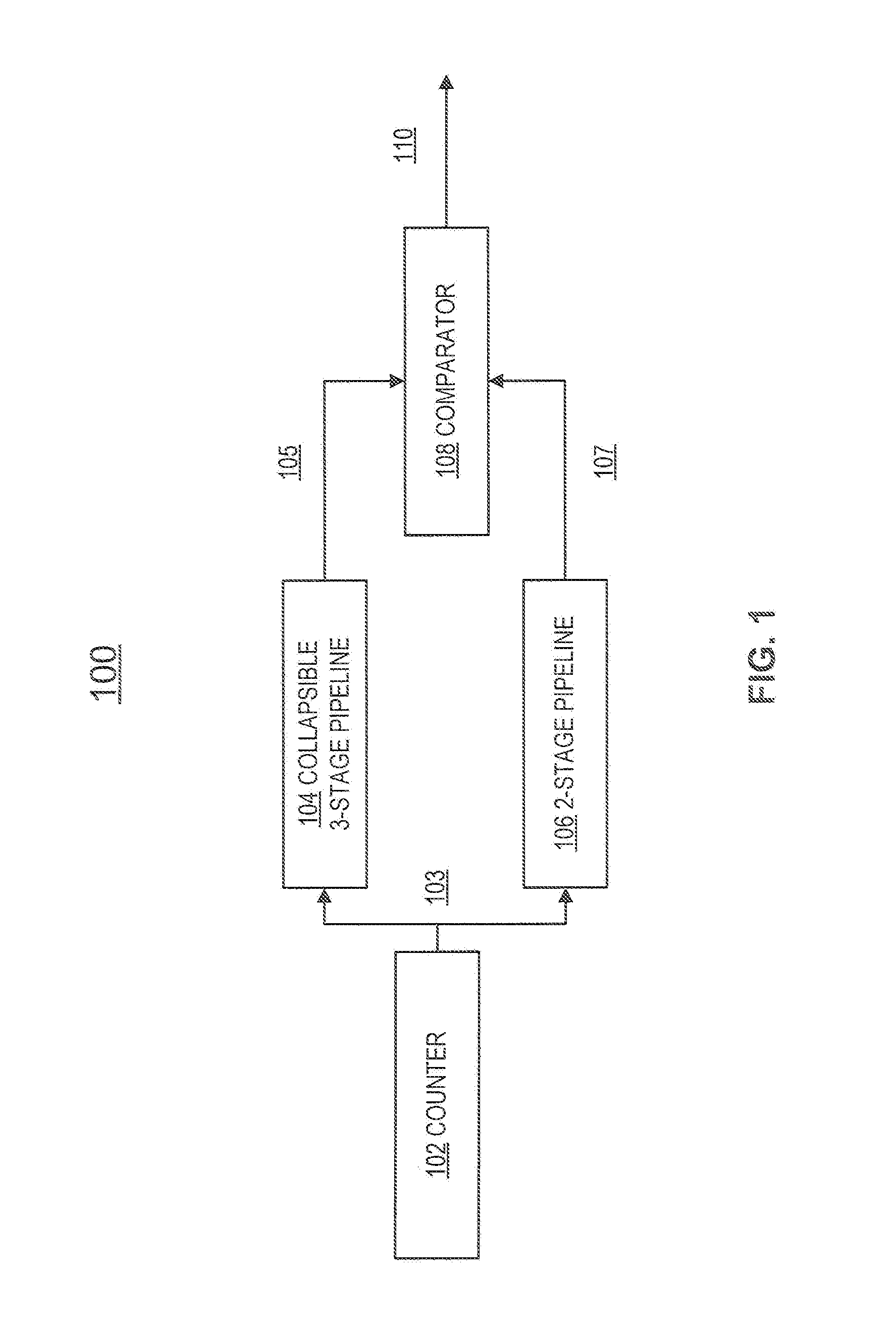
The present invention relates to a phase detector that can detect the phase of multiple clock signals. The phase detector has multiple registers, and each register has its own clock signal with specific edges. The edges of the clock signals can align with each other to create a pipeline of stages, or they can be misaligned. The misalignment can cause the stages to collapse into a single stage. The invention also includes a counter and a comparator to determine if collapse has occurred and to compare the output of two different stages to determine if they are aligned with each other. The technical effect of the invention is to enable accurate detection of the phase of multiple clock signals.

Problems solved by technology

The signals to and from the PLL often have to travel a long distance, and variation along the signal path causes increased loss of the useful portion of the clock cycle.
Moreover, field-programmable gate arrays (FPGAs) sometimes have limited clock generation options, and clock signals in an FPGA sometimes require being routed a long distance on the integrated circuit before being distributed to the subsystem that makes use of the clock signals.
This long distance causes and exacerbates an uncertainty between related clock signals when they arrive at the subsystem.
This effectively reduces the remaining useful clock period.

Method used


Image

  • Systems and methods for clock alignment using pipeline stages
  • Systems and methods for clock alignment using pipeline stages
  • Systems and methods for clock alignment using pipeline stages

Examples


Embodiment Construction

[0024]The systems and methods of the present invention include a circuit for clock alignment on an integrated circuit. In an ASIC or ASSP, a generation circuit may be used to create various clock signals, which may be distributed locally. However, on an FPGA, clock generation is limited because clocks have to be distributed very precisely, and specific resources may be needed to perform the distribution. Moreover, an FPGA is configurable, such that the clocks to be used in an FPGA may also need to be configurable. However, as clocks become configurable, they may degrade.

[0025]In one example, clock sources may be required to originate at a small number of locations on the integrated circuit. This does not provide much flexibility to provide the clock signal into the portion of the circuit that uses the clock signal. Accordingly, in an FPGA, it is more likely that clock signals will be routed over a long distance before they are actually used in the circuit elements (such as flip flop...


PUM


Abstract

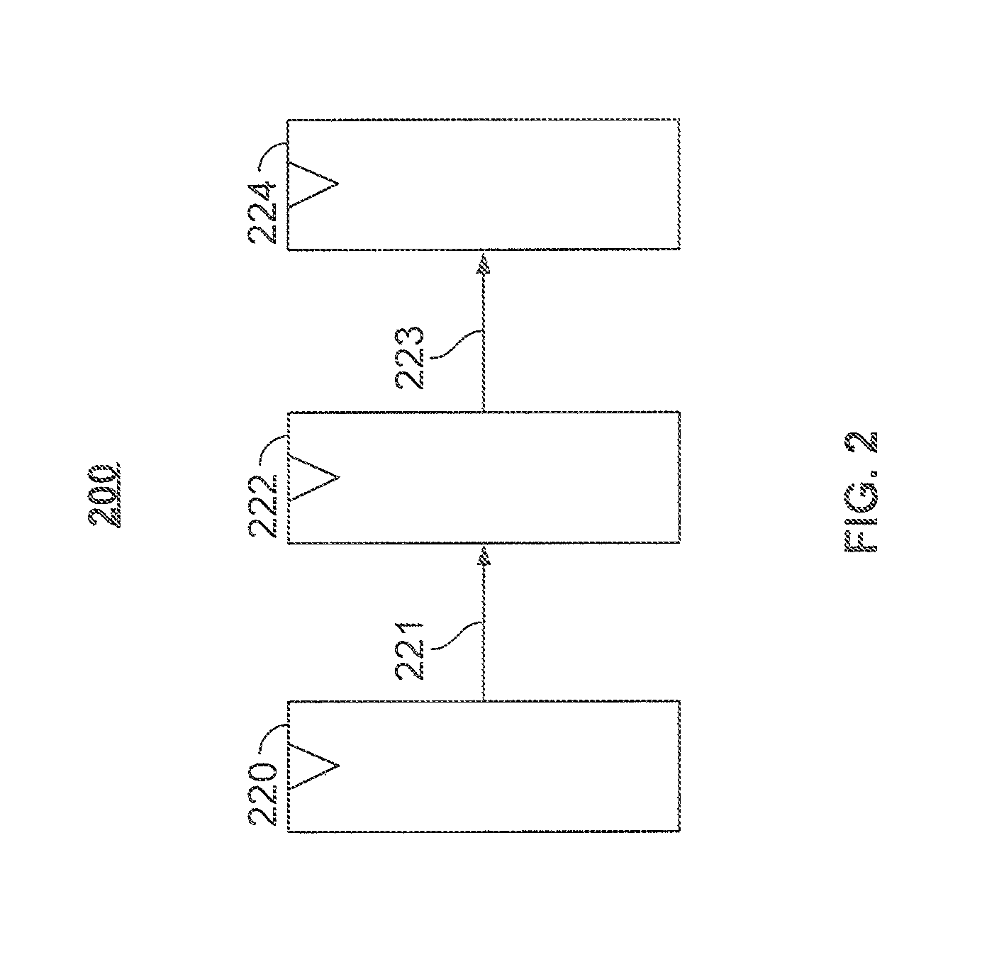
Systems and methods for phase detection are disclosed. A collapsible three-stage pipeline includes a first register in a first stage having a first clock signal having first clock edges, a second register in a second stage that receives a first signal from the first stage, and having a second clock signal having second clock edges, and a third register in a third stage that receives a second signal from the second stage, and having a third clock signal having third clock edges, wherein each second clock edge has a corresponding first clock edge and a corresponding third clock edge. The circuitry may further include a two-stage pipeline including fourth and fifth stages, a counter that provides an input signal into the collapsible three-stage pipeline and the two-stage pipeline, and a comparator that compares a first output of the collapsible three-stage pipeline and a second output of the two-stage pipeline.

Description

BACKGROUND OF THE INVENTION[0001]It is generally desirable to create integrated circuits that have clock signals that are aligned with each other to maintain synchrony across various components on the circuit. Often, systems may use multiple clock signals that have frequencies that are related to one another. For example, a system may use a first clock signal at a first frequency and a second clock signal at a second frequency that is an integer multiple (e.g., 2×, 3×, 4×, or any other suitable number) of the first frequency.[0002]A phase detector or a phase frequency detector may be used in a phase locked loop (PLL), and may be used to measure a difference in phase between two input signals. These require careful design and control of their physical implementation. Often, a PLL is placed on a separate chip from other components. The signals to and from the PLL often have to travel a long distance, and variation along the signal path causes increased loss of the useful portion of th...

Claims


Application Information

Patent Timeline
Patent Type & Authority Patents(United States)
IPC IPC(8): H03L7/06G06F1/12
CPCG06F1/12H04L7/0054H04L7/02
Inventor HOW, DANAEBELING, CARLKERTESZ, AUDREY CATHERINE
Owner ALTERA CORP
Learn More