This helps you quickly interpret patents by identifying the three key elements:
Problems solved by technology
Method used
Benefits of technology
Benefits of technology
The patent text describes a new electronic control system for a vehicle that uses humidity sensors to obtain information about the outside and inside air humidity. The system calculates the difference between the humidity before and after a dehumidification or humidification process and determines a soak time, which is the time needed for the humidity sensor to reach a stable reading. By adjusting this soak time based on the difference in humidity, the system ensures accurate and efficient failure detection of the humidity sensor, while preventing too much or too little humidity. This allows the vehicle to maintain optimal performance and safety.
Problems solved by technology
Therefore, failure of the humidity sensor may deteriorate the comfort in the vehicle, e.g., driver's comfort during the driving of the vehicle.
However, in the method disclosed in the patent document 1, it is unclear whether the length of the preset soak time is long enough against a variation of the humidity values obtained from the outside / inside air humidity sensors.
That is, failure detection accuracy of such method may not be necessarily high.
That is, when the number of failure detection opportunities decreases, the detection of failure may be delayed.
In addition, the vehicle may be used in very diverse environments with varying humidity levels and the required soak time for covering all the various environments may need to be very long.
Thus, a very long soak time may be too long for a vehicle used in a normal or average environment, i.e., decreasing the number of failure detection opportunities too much, and may delay the detection of a failure of the humidity sensor in the vehicle
That is, too few frequencies and too many frequencies of a failure detection operation are both limited and / or prevented.
Method used
Image
Click on the blue label to locate the original text in one second.
Reading with bidirectional positioning of images and text.
Examples
first embodiment
[0019]The first embodiment of the present disclosure, including the outline configuration of an electronic control unit for the present embodiment is described with reference to FIGS. 1 and 2.
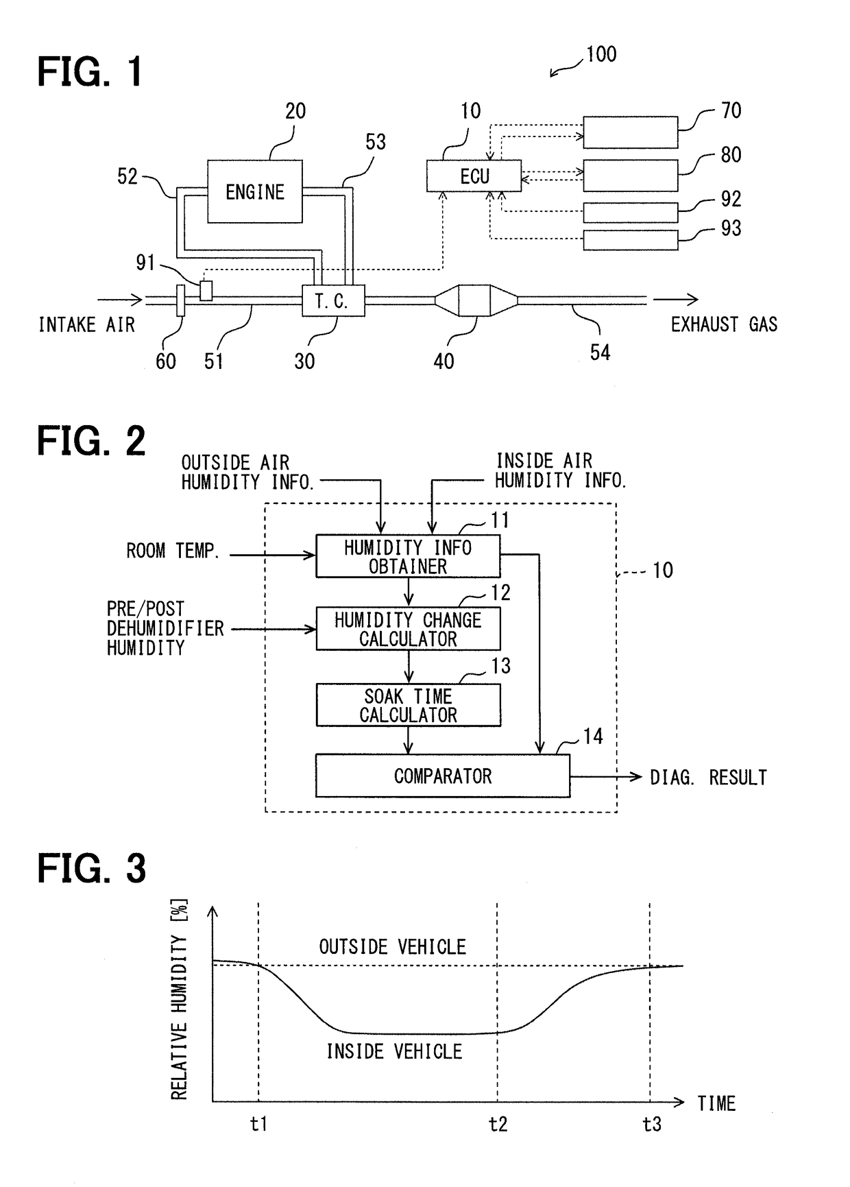
[0020]The electronic control unit in the present embodiment is an electronic device which controls an internal-combustion engine in a vehicle such as, for example, an engine control ECU. This electronic control unit performs control of an internal-combustion engine and an air-conditioner based on the information on humidity, which may be derived from communication with the humidity sensors disposed outside and inside of a passenger compartment. That is, the ECU and the humidity sensors are communicably connected. Further, the ECU performs control for diagnosing the humidity sensor.
[0021]As shown in FIG. 1, an electronic control unit 10 constitutes a part of an engine control system 100. That is, the engine control system 100 is provided with the electronic control unit 10, an engine 20, a turbo...
second embodiment
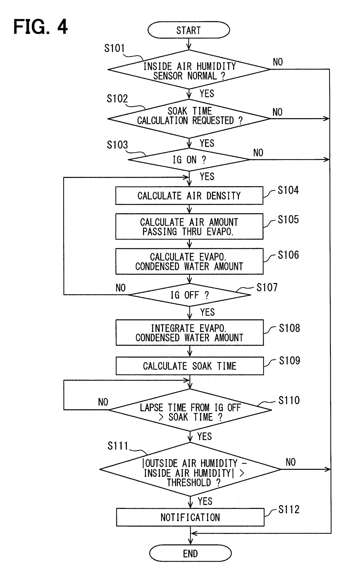
[0063]In the first embodiment, an example of the soak time variably changed depending on the amount of dehumidification is described. That is, in the first embodiment, the humidity change calculator 12 uses the water content in the passenger compartment as a physical quantity correlated with humidity, and the amount of dehumidification is used as the difference between two physical quantities, before and after dehumidification.
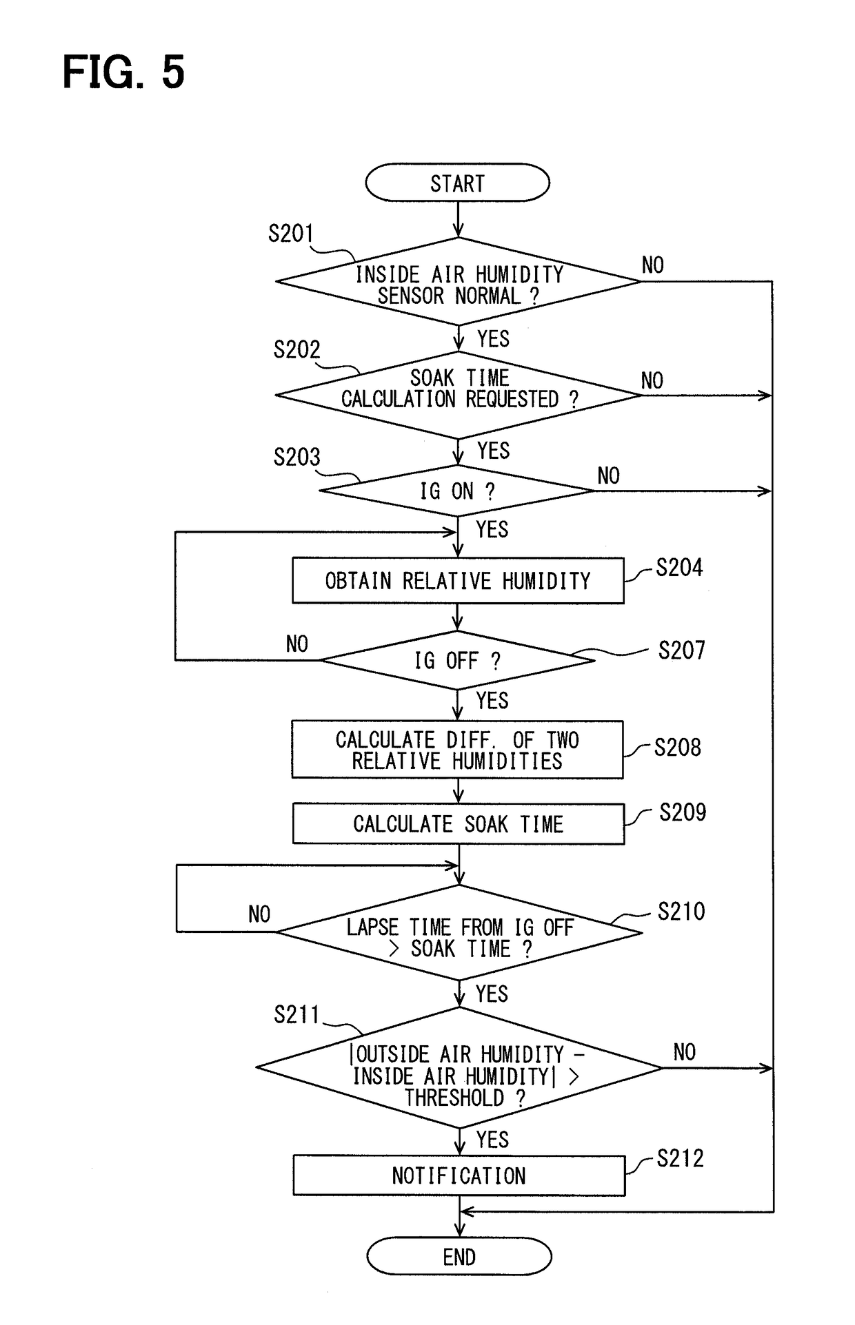
[0064]On the other hand, in the present embodiment, the relative humidity detected by the inside air humidity sensor 92 is used for the electronic control unit 10 as a physical quantity correlated with humidity. Although the electronic control unit 10 in the present embodiment has the same configuration as the first embodiment, i.e., has the humidity change calculator 12, it does not have to receive the information on humidity of the air before and after passing the evaporator from the air-conditioner system 70.
[0065]With reference to FIG. 5, the operation flo...
third embodiment
[0074]Although, in the first embodiment and the second embodiment, the electronic control unit 10 is described as the one, which performs the diagnosis of the outside air humidity sensor 91 by using the physical quantity difference mainly correlated with the humidity at the time of dehumidification by the air-conditioner system 70, the electronic control unit 10 can also perform the diagnosis of the outside air humidity sensor 91 by performing an intentional humidification with a humidifier.
[0075]Specifically, in the engine control system 100 described with reference to FIG. 1 in the first embodiment, the air-conditioner system 70 may be replaced with a humidifier system. The humidifier system includes a humidifier which supplies vapor or mist (e.g., a humidified air) into the passenger compartment. The humidifier may use any publicly-known humidifying method, such as an evaporation method, an ultrasonic method, a steam fan method, and the like, for example.
[0076]As an operation flo...
PUM
Abstract
An electronic control unit (ECU) obtains outside air humidity information from a sensor disposed outside a vehicle compartment and inside air humidity information from a sensor inside the vehicle compartment. The ECU includes a humidity information obtainer obtaining the inside air humidity information, a humidity change calculator calculating the inside air humidity information as a difference between (i) a physical quantity correlated with humidity before a start of a dehumidification or a humidification and (ii) a physical quantity correlated with humidity after a switch-off of the dehumidification or the humidification, a soak time calculator calculating, based on the difference of the physical quantities, a soak time from the switch-off of the dehumidification or the humidification to a sensor-diag startable time at which a diagnosis of the outside air humidity sensor is startable, and a comparator comparing the outside air humidity information and the inside air humidity information after a lapse of the soak time from the switch-off of the dehumidification or the humidification.
Description
CROSS REFERENCE TO RELATED APPLICATION[0001]The present application is based on and claims the benefit of priority of Japanese Patent Application No. 2017-103928, filed on May 25, 2017, the disclosure of which is incorporated herein by reference.TECHNICAL FIELD[0002]The present disclosure generally relates to an electronic control unit that controls a humidity sensor.BACKGROUND INFORMATION[0003]An electronic control unit used in a vehicle for controlling an internal-combustion engine typically obtains physical quantities from an environment in which the vehicle travels, for a control of a drive of the internal-combustion engine. Humidity is one of such quantities. Since the internal-combustion engine mixes outside air taken in from the environment and fuel for the combustion, the electronic control unit needs to control the combustion based on the humidity of the outside air for an appropriate drive of the engine. Further, the electronic control unit also needs to refer to inside ai...
Claims
Application Information
Patent Timeline
Application Date:The date an application was filed.
Publication Date:The date a patent or application was officially published.
First Publication Date:The earliest publication date of a patent with the same application number.
Issue Date:Publication date of the patent grant document.
PCT Entry Date:The Entry date of PCT National Phase.
Estimated Expiry Date:The statutory expiry date of a patent right according to the Patent Law, and it is the longest term of protection that the patent right can achieve without the termination of the patent right due to other reasons(Term extension factor has been taken into account ).
Invalid Date:Actual expiry date is based on effective date or publication date of legal transaction data of invalid patent.

