
Compact antenna system with reduced multipath reception

a multi-path reception and compact technology, applied in the field of antennas, can solve problems such as errors in time delay measurements and carrier phase measurements, errors in position determination, and uncorrected errors

Active Publication Date: 2016-11-22
TOPCON POSITIONING SYST INC
View PDF5 Cites 1 Cited by
  • Summary
  • Abstract
  • Description
  • Claims
  • Application Information

AI Technical Summary

Problems solved by technology

A major source of the uncorrected errors is multipath reception by the receiving antenna.
The reflected signals are processed along with the direct signals and cause errors in the time delay measurements and errors in the carrier phase measurements.
These errors subsequently cause errors in position determination.

Method used


Image

  • Compact antenna system with reduced multipath reception
  • Compact antenna system with reduced multipath reception
  • Compact antenna system with reduced multipath reception

Examples


Embodiment Construction

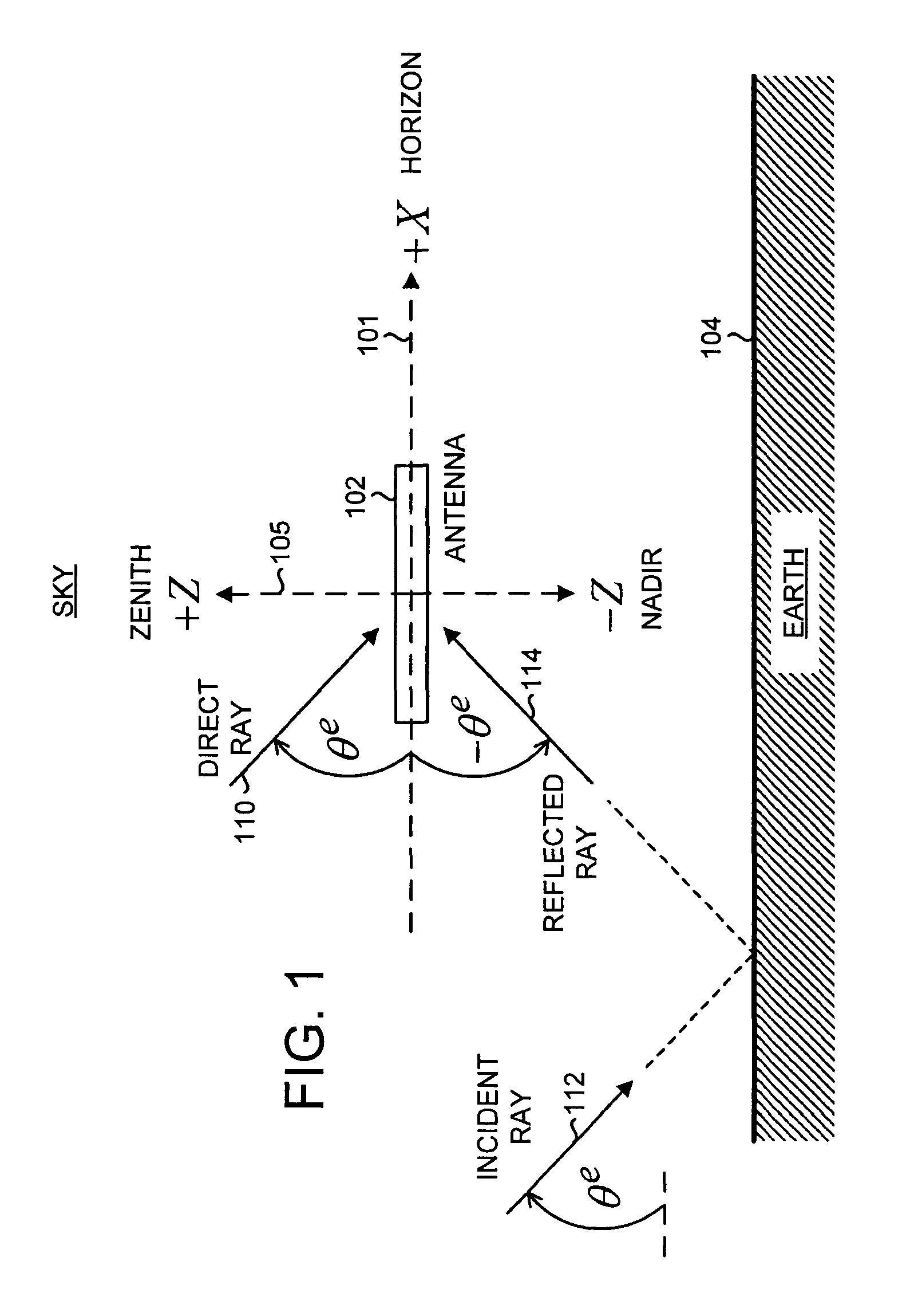
[0033]FIG. 1 shows a schematic of an antenna 102 positioned above the Earth 104. Herein, the term Earth includes both land and water environments. To avoid confusion with “electrical” ground (as used in reference to a ground plane), “geographical” ground (as used in reference to land) is not used herein. To simplify the drawing, supporting structures for the antenna are not shown. Shown is a reference Cartesian coordinate system with X-axis 101 and Z-axis 105. The Y-axis (not shown) points into the plane of the figure. In an open-air environment, the +Z (up) direction, referred to as the zenith, points towards the sky, and the −Z (down) direction, referred to as the nadir, points towards the Earth. The X-Y plane lies along the local horizon plane.

[0034]In FIG. 1, electromagnetic waves are represented by rays with an elevation angle θe with respect to the horizon. The horizon corresponds to θe=0 deg; the zenith corresponds to θe=+90 deg; and the nadir corresponds to θe=−90 deg. Rays ...


PUM


Abstract

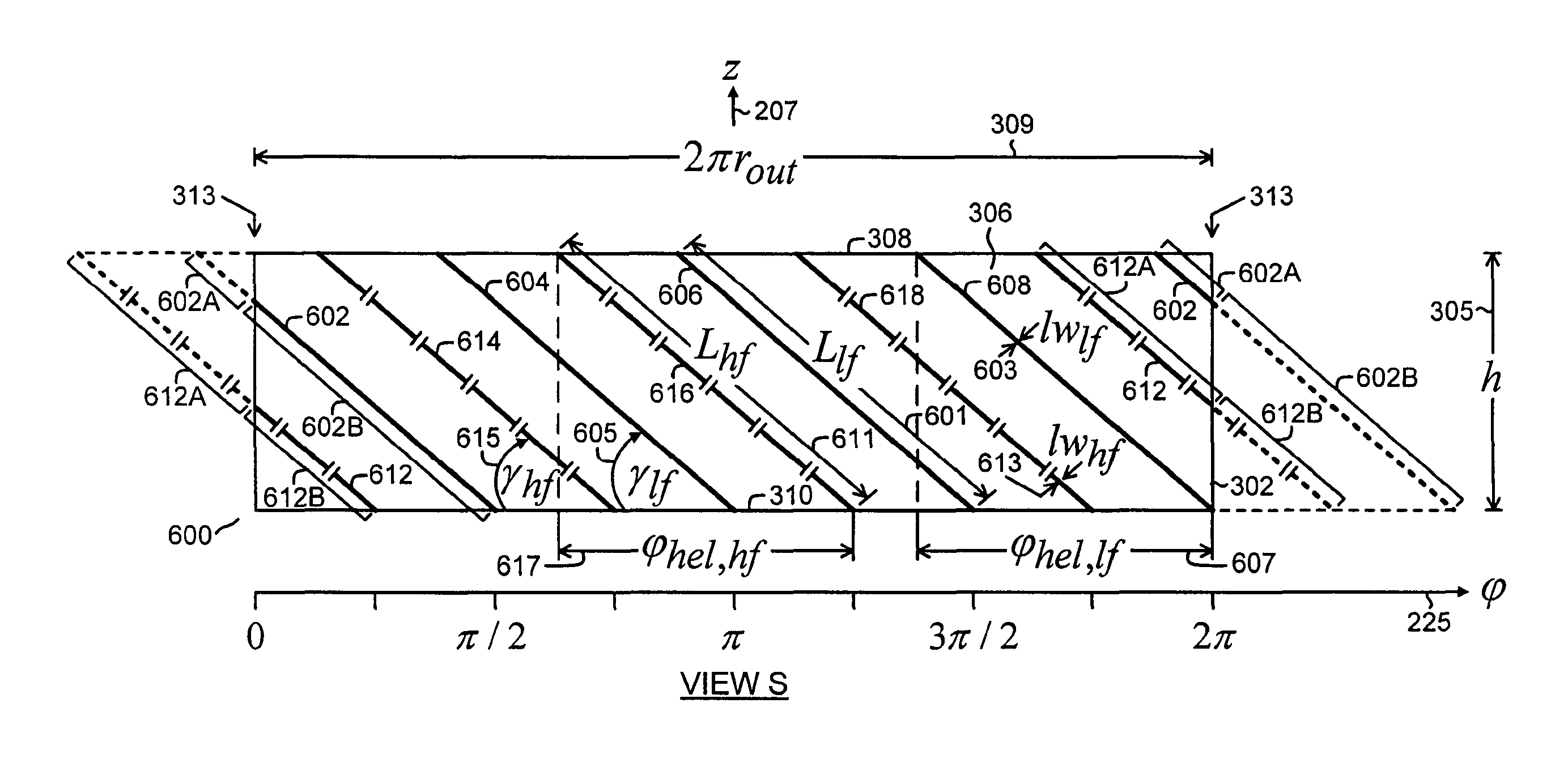
An antenna is configured to operate with circularly-polarized electromagnetic radiation in a low-frequency band and in a high-frequency band. The antenna comprises a ground plane and a radiator. The radiator comprises four pairs of radiating elements disposed as pairs of spiral segments on a cylindrical surface having a longitudinal axis orthogonal to the ground plane. Each pair of radiating elements comprises a low-frequency radiating element and a high-frequency radiating element. The low-frequency radiating element comprises a low-frequency conductive strip. The high-frequency radiating element comprises an electrically-connected series of at least one high-frequency conductive strip and at least one high-frequency capacitor. The electrical path lengths of the low-frequency radiating elements and the electrical path lengths of the high-frequency radiating elements are equal.

Description

CROSS-REFERENCE TO RELATED APPLICATIONS[0001]This application is a national stage (under 35 U.S.C. 371) of International Patent Application No. PCT / RU2013 / 001052, filed Nov. 22, 2013, which is herein incorporated by reference in its entirety.BACKGROUND OF THE INVENTION[0002]The present invention relates generally to antennas, and more particularly to antennas for global navigation satellite systems.[0003]Global navigation satellite systems (GNSSs) can determine locations with high accuracy. Currently deployed global navigation satellite systems are the United States Global Positioning System (GPS) and the Russian GLONASS. Other global navigation satellite systems, such as the European GALILEO system, are under development. In a GNSS, a navigation receiver receives and processes radio signals transmitted by satellites located within a line-of-sight of the receiver. The satellite signals comprise carrier signals modulated by pseudo-random binary codes. The receiver measures the time d...

Claims


Application Information

Patent Timeline
Patent Type & Authority Patents(United States)
IPC IPC(8): H01Q1/36H01Q5/321H01Q11/08
CPCH01Q5/321H01Q1/36H01Q11/08
Inventor STEPANENKO, ANTON PAVLOVICHTATARNIKOV, DMITRY VITALIEVICHASTAKHOV, ANDREY VITALIEVICH
Owner TOPCON POSITIONING SYST INC
Learn More