Disc brake rotor for heavy-duty vehicles

a disc brake and rotor technology, applied in the direction of brake types, brake discs, mechanical devices, etc., can solve the problems of significant thermal stress on the disc portion of the rotor, reduce the performance and life of the rotor, and significant heat, etc., and achieve the effect of increasing air flow

Active Publication Date: 2016-11-29
HENDRICKSON USA L L C
View PDF65 Cites 14 Cited by
  • Summary
  • Abstract
  • Description
  • Claims
  • Application Information

AI Technical Summary

Benefits of technology

[0018]An objective of the present invention is to provide a rotor of a disc brake for heavy-duty vehicles that provides means of interconnecting the inboard disc and the outboard disc of the rotor to increase air flow beyond that of vane-type connections.
[0019]Another objective of the present invention is to provide a rotor of a disc brake for heavy-duty vehicles that provides means of connecting the rotor disc portion to the rotor sleeve that reduces coning of the rotor during braking.
[0020]Still another objective of the present invention is to provide a rotor of a disc brake for heavy-duty vehicles that includes a metallurgical composition which desirably maintains the heat transfer properties of the rotor while decreasing the brittleness and improving the hot strength of the rotor.
[0021]Yet another objective of the present invention is to provide a rotor of a disc brake for heavy-duty vehicles that improves the resistance of the rotor to thermal stress created during braking, thereby increasing the performance and the life of the rotor and increasing the life of the brake pads.

Problems solved by technology

This forcing of the brake pad friction material against the disc portion of the rotor during braking generates a significant amount of heat, which in turn creates significant thermal stresses on the disc portion of the rotor.
It is well known in the art that significant thermal stresses tend to decrease the performance and the life of the rotor.
However, vane-type connections may not actually optimize air flow between the inboard and outboard discs.
Such uneven contact between the inboard disc and its adjacent brake pad, and the outboard disc and its adjacent brake pad, reduces the efficiency of the brake system.
In addition, such uneven contact may create stress areas at each point of uneven contact between the brake pads and the inboard and outboard discs, which may cause the formation of cracks in the rotor disc portion, thereby reducing the life of the rotor.
Such uneven contact between the inboard disc and its adjacent brake pad, and the outboard disc and its adjacent brake pad, also undesirably reduces the life of the brake pads.
Such additional coning undesirably increases uneven contact between the inboard disc and its adjacent brake pad, and the outboard disc and its adjacent brake pad, further reducing the efficiency of the brake system and the life of the brake pads.
Moreover, an increase in such uneven contact may undesirably increase the stress at each point of uneven contact between the brake pads and the respective inboard and outboard discs, which may in turn increase the formation of cracks in the rotor disc portion, thereby further reducing the life of the rotor.
While such a high carbon content has provided good heat transfer properties, it creates a rotor that is undesirably brittle.
When a rotor is brittle, it has little ability to resist high temperature stresses, and as a result, prior art rotors with a high carbon content may undesirably experience crack initiation and propagation.
In addition, such a high carbon content undesirably reduces the strength of the rotor at elevated temperatures, which is also referred to in the art as a reduction of the rotor's hot strength.

Method used


Image

  • Disc brake rotor for heavy-duty vehicles
  • Disc brake rotor for heavy-duty vehicles
  • Disc brake rotor for heavy-duty vehicles

Examples


first embodiment

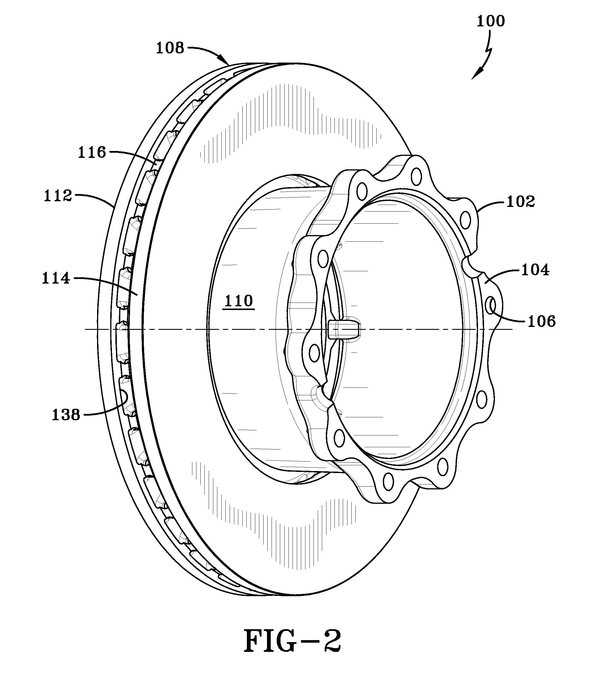
[0057]the improved disc brake rotor for heavy-duty vehicles of the present invention is indicated generally at 100 and is shown in FIGS. 2-7. As will be described in detail below, rotor 100 of the present invention includes an inboard attachment to a rotor sleeve and thus to a hub of a wheel end assembly, which reduces coning of the rotor during braking. Rotor 100 of the present invention also includes pins that interconnect inboard and outboard discs of the rotor, which increase air flow between the discs beyond that of prior art vane-type connections. Moreover, rotor 100 of the present invention includes an improved metallurgical composition that desirably maintains the heat transfer properties of the rotor while decreasing the brittleness of the rotor and improving the hot strength of the rotor. These features cooperate to improve the resistance of rotor 100 to thermal stress created during braking, thereby increasing the performance and the life of the rotor, and also increasing...

second embodiment

[0079 rotor 160, by employing pins 116′, increases air flow through rotor disc portion 108′, which dissipates heat and reduces thermal loading of the disc portion.

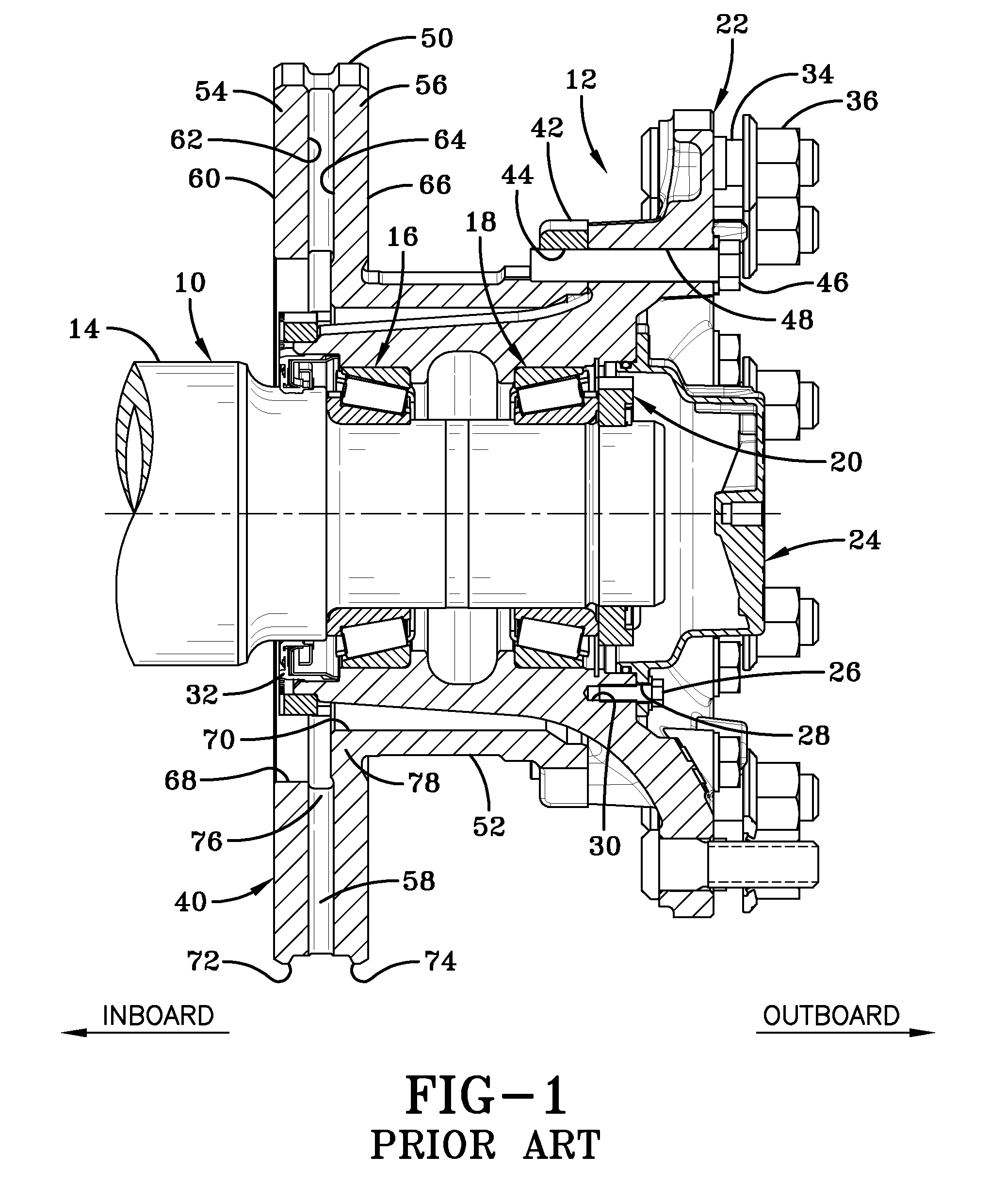
[0080]Reduction of thermal loading of rotor disc portion 108′ reduces potential cracking of rotor 160, thereby improving the performance and the life of the rotor. In addition, pins 116′ create a discontinuous radial connection between inboard disc 112′ and outboard disc 114′, compared to continuously connected radially-extending vanes 58 of the prior art. In the event a crack forms on inboard disc 112′ and / or outboard disc 114′, the discontinuous radial connection created by pins 116′ acts to prevent propagation of the crack, thereby further improving the performance and the life of rotor 160.

[0081]Referring now to FIGS. 11 and 12, a third embodiment of the improved disc brake rotor for heavy-duty vehicles of the present invention is shown and indicated generally at 170. Third embodiment rotor 170 is similar in structure ...

fourth embodiment

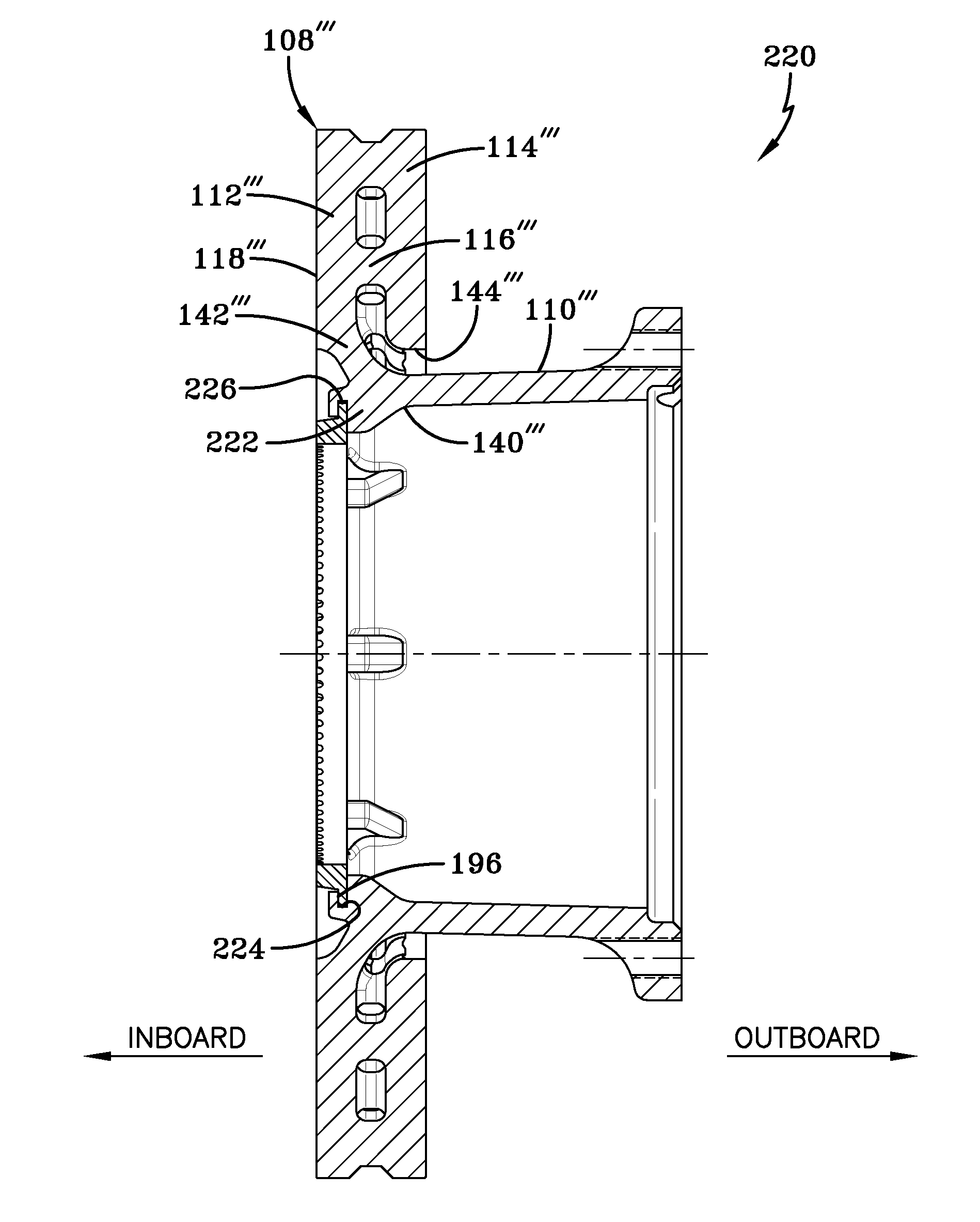
[0092 rotor 220 thus may be formed to accept a discrete tone ring 180, which may be formed of a different material than the rotor. Use of a discrete tone ring 180 reduces corrosion issues in particular circumstances, enables the tone ring to be removed for servicing, and desirably reduces weight when compared to integrally-formed tone ring 152 (FIG. 4).

[0093]In this manner, the construction and arrangement of the improved disc brake rotor 100, 160, 170, 220 for heavy-duty vehicles of the present invention provides an inboard connection 140, 140′, 140″, 140′″ of disc portion 108, 108′, 108″, 108′41 to sleeve 110, 110′, 110″, 110′″, which reduces or eliminates coning of the disc portion due to the heat from braking. Such a reduction or an elimination of coning optimizes the efficiency of the brake system, and desirably reduces the stress at each point of contact between the brake pads and each respective inboard disc 112, 112′, 112″, 112′″ and outboard disc 114, 114′, 114″, 114′″. Th...


PUM

PropertyMeasurementUnit
diameteraaaaaaaaaa
diameteraaaaaaaaaa
diameteraaaaaaaaaa

Abstract

The invention is directed to a rotor of a disc brake system for heavy-duty vehicles. The rotor includes an inboard disc and an outboard disc. The outboard disc is spaced apart from the inboard disc, and a plurality of pins extends between and rigidly connects the inboard disc and the outboard disc. A sleeve includes an inboard end and an outboard end, and is disposed inside an inner perimeter of the outboard disc. A connecting member extends between and rigidly connects an inner perimeter of the inboard disc to the inboard end of the sleeve. The inboard disc attachment to the sleeve and the interconnecting pins cooperate to improve the resistance of the rotor to thermal stress created during braking, thereby increasing the performance and the life of the rotor.

Description

CROSS-REFERENCE TO RELATED APPLICATIONS[0001]This application claims the benefit of U.S. Provisional Patent Application Ser. No. 61 / 856, 097, which was filed on Jul. 19, 2013.BACKGROUND OF THE INVENTION[0002]Technical Field[0003]The invention relates to the art of disc brakes for heavy-duty vehicles. More particularly, the invention relates to rotors of disc brakes for heavy-duty vehicles. Still more particularly, the invention is directed to a rotor of a disc brake, which includes an inboard attachment to a sleeve, pins that interconnect inboard and outboard discs of the rotor, and an improved metallurgical composition, all of which cooperate to improve the resistance of the rotor to thermal stress created during braking, thereby increasing the performance and the life of the rotor.[0004]Background Art[0005]Disc brake systems for vehicles are well known in the brake art. Such systems operate by forcing a pair of opposing brake pads against a rotor, thereby creating friction between...

Claims


Application Information

Patent Timeline
Patent Type & Authority Patents(United States)
IPC IPC(8): F16D65/12F16D65/847F16D66/00F16D65/02
CPCF16D65/128F16D65/847F16D2065/132F16D2065/1328F16D2066/003F16D65/12F16D2065/1364F16D2065/1376F16D2065/1392C21D5/00C22C37/10C22C37/00
Inventor WHITE, JAY D.MORRIS, JEFFREY S.
Owner HENDRICKSON USA L L C
Why Eureka
Try Eureka