Cycle wheel rim and method of manufacture

a cycle wheel and rim technology, applied in the direction of bicycles, mechanical equipment, transportation and packaging, etc., can solve the problems of reducing the thickness of the rim, breaking the extrusion die, and significant plastic deformation, so as to reduce the weight of the rim, improve rigidity, and manufacture quickly

Inactive Publication Date: 2016-12-06
MAVIC SA
View PDF24 Cites 0 Cited by
  • Summary
  • Abstract
  • Description
  • Claims
  • Application Information

AI Technical Summary

Benefits of technology

[0015]The foregoing are drawbacks that the present invention overcomes, particularly by providing a cycle wheel rim incorporating a rim brake system and a method for manufacturing such a rim, which makes it possible to reduce the weight of the rim while optimizing rigidity. In addition, the rim according to the invention can be manufactured quickly, and the manufacturing method prevents the occurrence of defects during the extrusion and bending of the section.
[0016]The useful life of rims is often limited by the appearance of cracks in the spoke fastening zone. Once they occur, such cracks propagate very quickly in the spinning direction, quickly causing a rupture of the bridge. This well-known fatigue phenomenon is due to the numerous load cycles to which the spokes are subjected at each turn of the wheel, on the one hand, and it is also accelerated by small surface defects which typically are longitudinal striations caused by friction of the metal in the die during the spinning operation, on the other hand. The invention therefore also optimizes the fatigue strength of the rim by locally reinforcing the fastening of the spoke, but also by improving the surface finish in order to eliminate or delay the initiation of fatigue cracks.
[0019]In accordance with the invention, when the pad is not worn out, the sound produced by the friction of the pad is constant throughout braking. Conversely, when the pad is worn out, the sound produced by the friction changes when the pad rubs in the area of each zone of the braking surface which has a variation in height. This difference in sound enables the user to determine, during braking, whether the pad is worn out.
[0038]The manufacturing method is standardized, that is to say, it is possible to easily manufacture rims of various geometries from the same section without the need to change the tools provided for the extruding, bending, and machining. For example, for the manufacture of a line of rims, make various front and rear wheel rims can be made from the same section and using the same machining tools.
[0039]It is known that fatigue cracks generally occur in the area of the bridge of the rim, around the spoke fastening zones. If a rim made by such a method proves to be insufficiently strong, the thickness of the bridge of the rim can easily be increased, at least in the area of certain zones of the circumference of the rim, by keeping the initial tools and by varying the geometric parameters of the machining. For example, if the rim is machined with a milling cutter having a concave profile, it suffices to shift the milling cutter toward the axis of rotation of the rim to increase the thickness of its walls. Thus, the rim development costs are reduced.

Problems solved by technology

Thus, for alloys that are typically used in the manufacture of rims, it is very risky to go below thicknesses of 0.85 mm, as doing so may quickly break the extrusion die.
In addition, the bending of a section causes significant plastic deformations, particularly in the zones that are away from the center of gravity of the cross section.
These substantial plastic deformations cause dislocations of the grains of the material which, in turn, can result in a surface finish known as “orange peel,” which is often considered unsightly.
Furthermore, overly thin lateral walls also generate local buckling of the walls of the section during bending, when subject to overly high compressive deformations.
This manufacturing method is relatively cumbersome to implement and, although the surface finish does become uniform, it remains quite rough.
Reducing the weight of the rim is not optimal because the bridge of the rim retains its initial thickness.
The machining is time-intensive and it is complex to implement, because it requires the use of a five-axis machine.
This leads to additional development costs and does not standardize the manufacturing method.
In addition, known cycle wheels, intended for use with a rim brake system, do not enable the user to detect wear on the brake pads.
Braking is ineffective if the pad used on the cycle is worn out, which can be dangerous, and the support on which the pad is mounted may become damaged and may damage the rim.
The useful life of rims is often limited by the appearance of cracks in the spoke fastening zone.
Once they occur, such cracks propagate very quickly in the spinning direction, quickly causing a rupture of the bridge.
This well-known fatigue phenomenon is due to the numerous load cycles to which the spokes are subjected at each turn of the wheel, on the one hand, and it is also accelerated by small surface defects which typically are longitudinal striations caused by friction of the metal in the die during the spinning operation, on the other hand.
It is known that fatigue cracks generally occur in the area of the bridge of the rim, around the spoke fastening zones.

Method used


Image

  • Cycle wheel rim and method of manufacture
  • Cycle wheel rim and method of manufacture
  • Cycle wheel rim and method of manufacture

Examples


Embodiment Construction

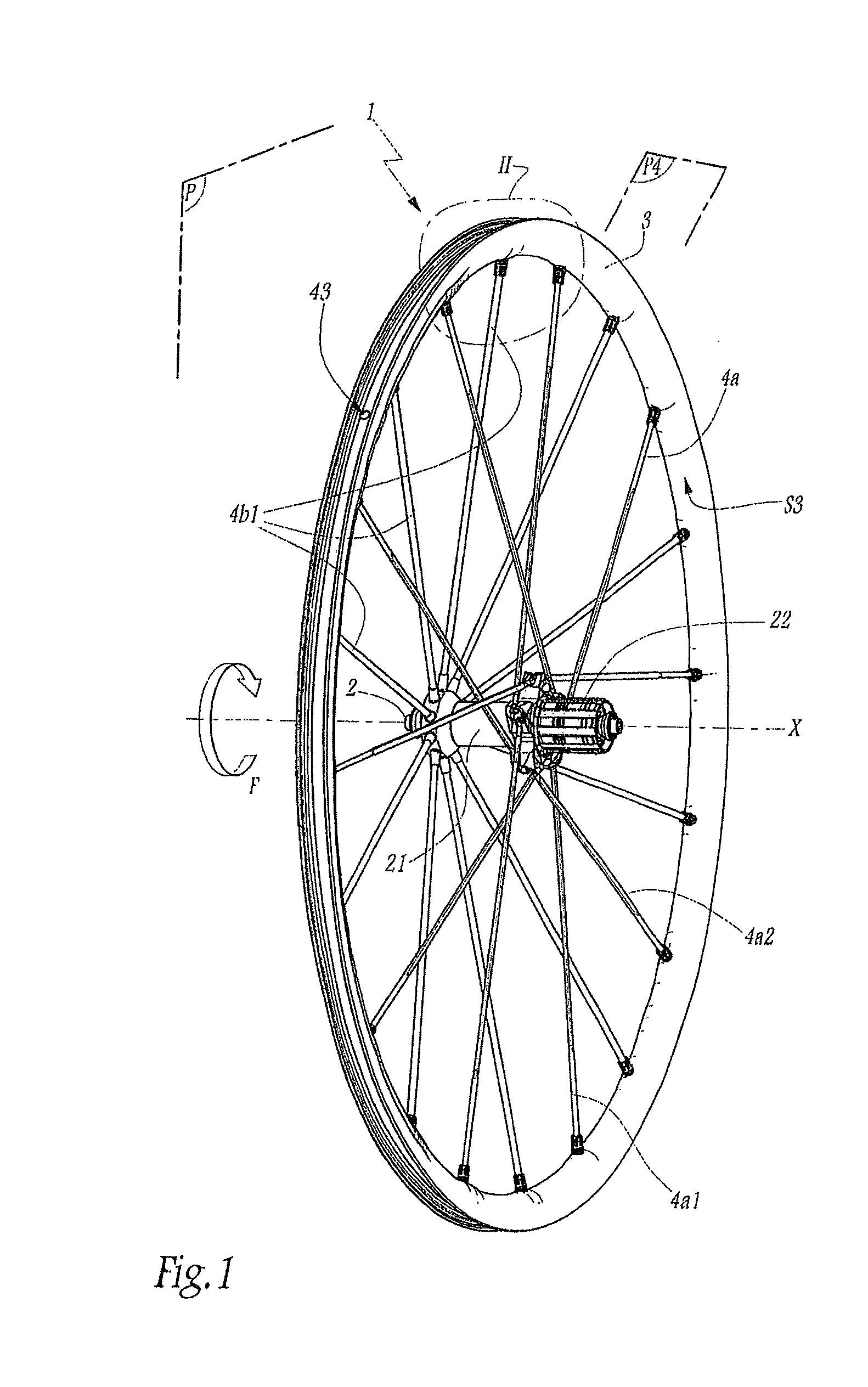
[0057]FIG. 1 shows a bicycle rear wheel 1, without a tire mounted thereon. The wheel 1 comprises two sets 4a, 4b of spokes 4a1, 4a2, 4b1 mounted on a rim 3. The spoke sets 4a, 4b are connected to a hub 2 of the wheel 1, which comprises a hub body 21 extending along an axis of rotation X of the wheel 1. A freewheel mechanism 22 is connected to one end of the hub body 21 which supports the spoke set 4a, and the other end of the hub body 21 supports the spoke set 4b. The freewheel mechanism 22 is provided to be assembled with a sprocket cassette (not shown).

[0058]When a cyclist pedals in the forward direction, the cyclist rotates the wheel 1 about the axis of rotation X through the sprocket cassette and the freewheel mechanism 22 in a direction designated by the arrow F in FIG. 1.

[0059]The spoke set 4a comprises driving spokes 4a2, which pull on the rim 3 when the cyclist pedals, and non-driving spokes 4a1, or pushing spokes, which tend to relax when the cyclist pedals. The spoke set 4...


PUM

PropertyMeasurementUnit
thicknessaaaaaaaaaa
thicknessesaaaaaaaaaa
thicknessaaaaaaaaaa

Abstract

The invention includes a rim for a cycle wheel, having a U-shaped radial cross section, with two lateral sidewalls and a bridge connecting the sidewalls and located so as to be opposite an axis rotation of the wheel. The sidewalls each define a planar braking surface, adapted to cooperate with a brake pad. The height of at least one braking surface, measured radially, is not constant over the circumference of the rim and has at least one variation in height.

Description

CROSS-REFERENCE TO RELATED APPLICATION[0001]This application is based upon French Patent Application No. 12 / 00027, filed Jan. 4, 2012, the disclosure of which is hereby incorporated by reference thereto in its entirety, and the priority of which is claimed under 35 U.S.C. §119.BACKGROUND[0002]1. Field of the Invention[0003]The invention relates to a rim for a cycle wheel, and a method for manufacturing such a rim.[0004]2. Background Information[0005]Conventionally, a cycle wheel rim is annular and has a U-shaped radial cross section, with two lateral sidewalls that are generally perpendicular to the axis of rotation of the wheel and a bridge that connects the lateral sidewalls and is oriented so as to be opposite the axis of rotation of the wheel. In the case of a spoked wheel, the spokes are generally fastened to the bridge of the rim.[0006]To manufacture a cycle wheel rim, it is known to make a rectilinear section by extruding or spinning a metal alloy, such as an aluminum alloy, ...

Claims


Application Information

Patent Timeline
Patent Type & Authority Patents(United States)
IPC IPC(8): B60B21/08B60B21/02B60B21/06B21D53/30
CPCB60B21/08B21D53/30B60B21/025B60B21/026B60B21/062B60B2310/211B60B2310/232B60B2310/234B60B2360/104B60B2360/1458B60B2900/321B60Y2200/13B60Y2200/134Y10T29/49526
Inventor ALEXANDRE, BERENGERMERCAT, JEAN-PIERRE
Owner MAVIC SA
Why Eureka
Try Eureka