Eureka AIR delivers breakthrough ideas for toughest innovation challenges, trusted by R&D personnel around the world.

Apparatus and methods for non-invasive closed loop step testing using a tunable trade-off factor

a non-invasive, step testing technology, applied in adaptive control, process and machine control, instruments, etc., can solve the problems of tunable trade-off between optimization and robustness, and the failure of full optimization at every cycle, so as to improve the process system model

Active Publication Date: 2016-12-06
ASPENTECH CORP
View PDF20 Cites 9 Cited by
  • Summary
  • Abstract
  • Description
  • Claims
  • Application Information

AI Technical Summary

Benefits of technology

[0011]Embodiments provide expansion of automated closed loop step testing techniques described in Assignee's U.S. Pat. No. 7,209,793 (Apr. 24, 2007). Embodiments can be configured and executed to generate required data for model quality assessment and / or model re-identification in Assignee's U.S. Patent Application Publication No. 2011 / 0130850 (published Jun. 2, 2011), while also minimizing negative impact to the underlying process operation, an improvement over the state of the art.
[0027]In yet another embodiment of the present invention, computer means repeatedly implements move plans with step testing signals and measures the response variables, and further improves the model of the process system.

Problems solved by technology

This indicates that pushing for full optimization at every cycle may not always produce a better result; sometimes maintaining the current targets yield a better overall result.
Results have indicated that there is a tunable tradeoff between optimization and robustness.
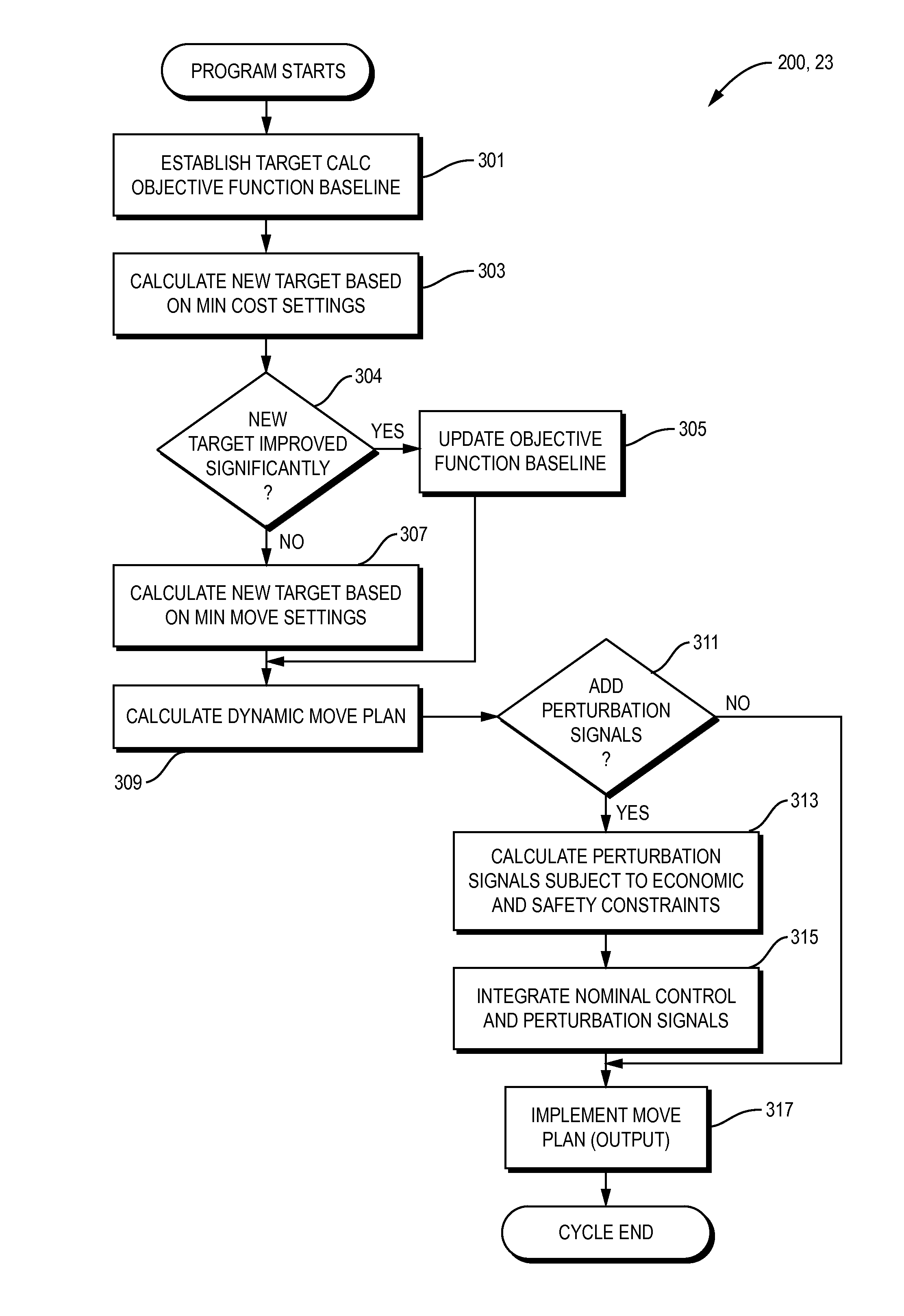
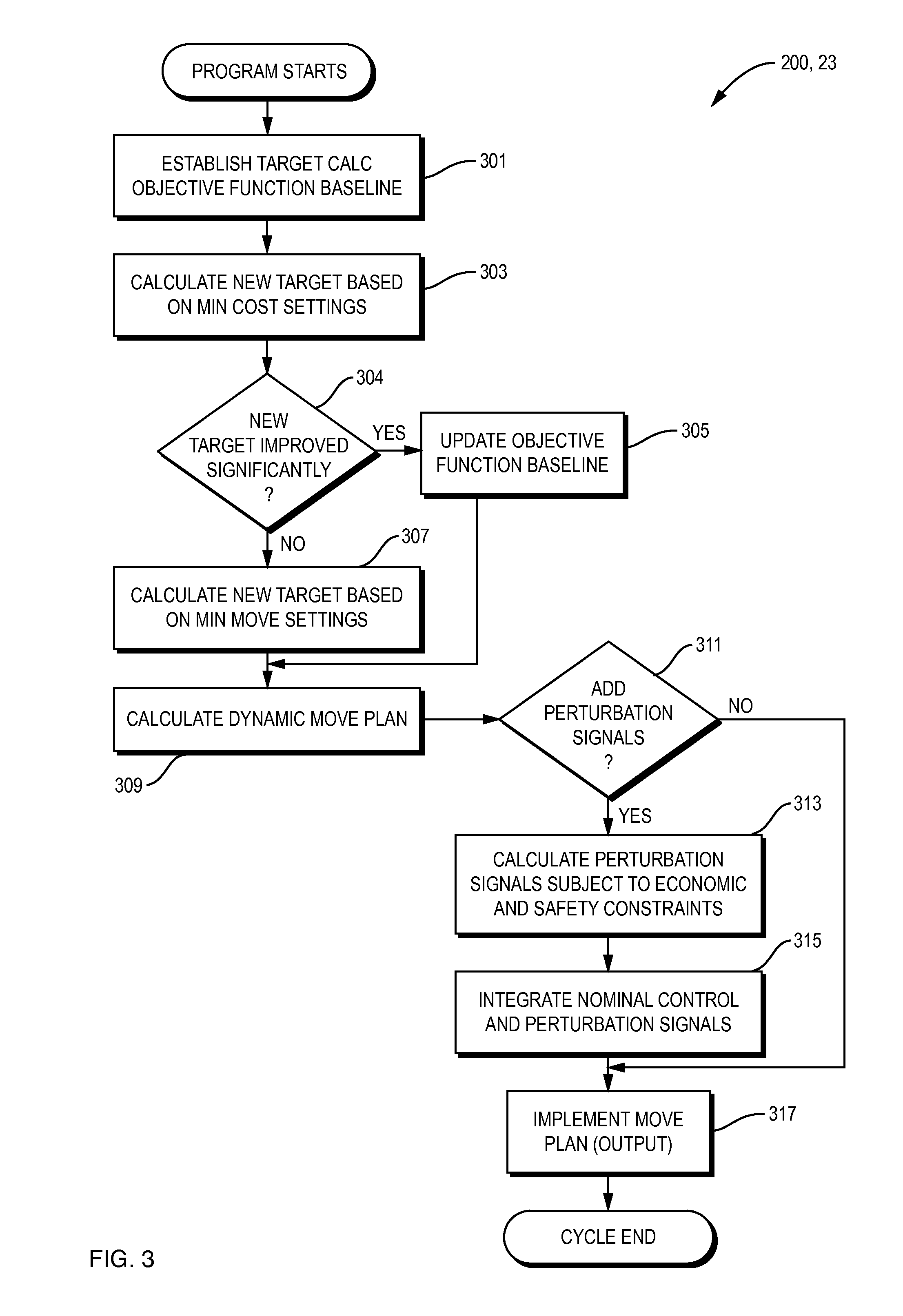
The challenge is on how to decide when the process controller engine should run in optimization mode (minimum cost criterion), and when it can run in a constrained step testing mode (using the minimum move criterion).

Method used


Image

  • Apparatus and methods for non-invasive closed loop step testing using a tunable trade-off factor
  • Apparatus and methods for non-invasive closed loop step testing using a tunable trade-off factor
  • Apparatus and methods for non-invasive closed loop step testing using a tunable trade-off factor

Examples


Embodiment Construction

[0035]A description of example embodiments of the invention follows.

[0036]The teachings of all patents, published applications and references cited herein are incorporated by reference in their entirety.

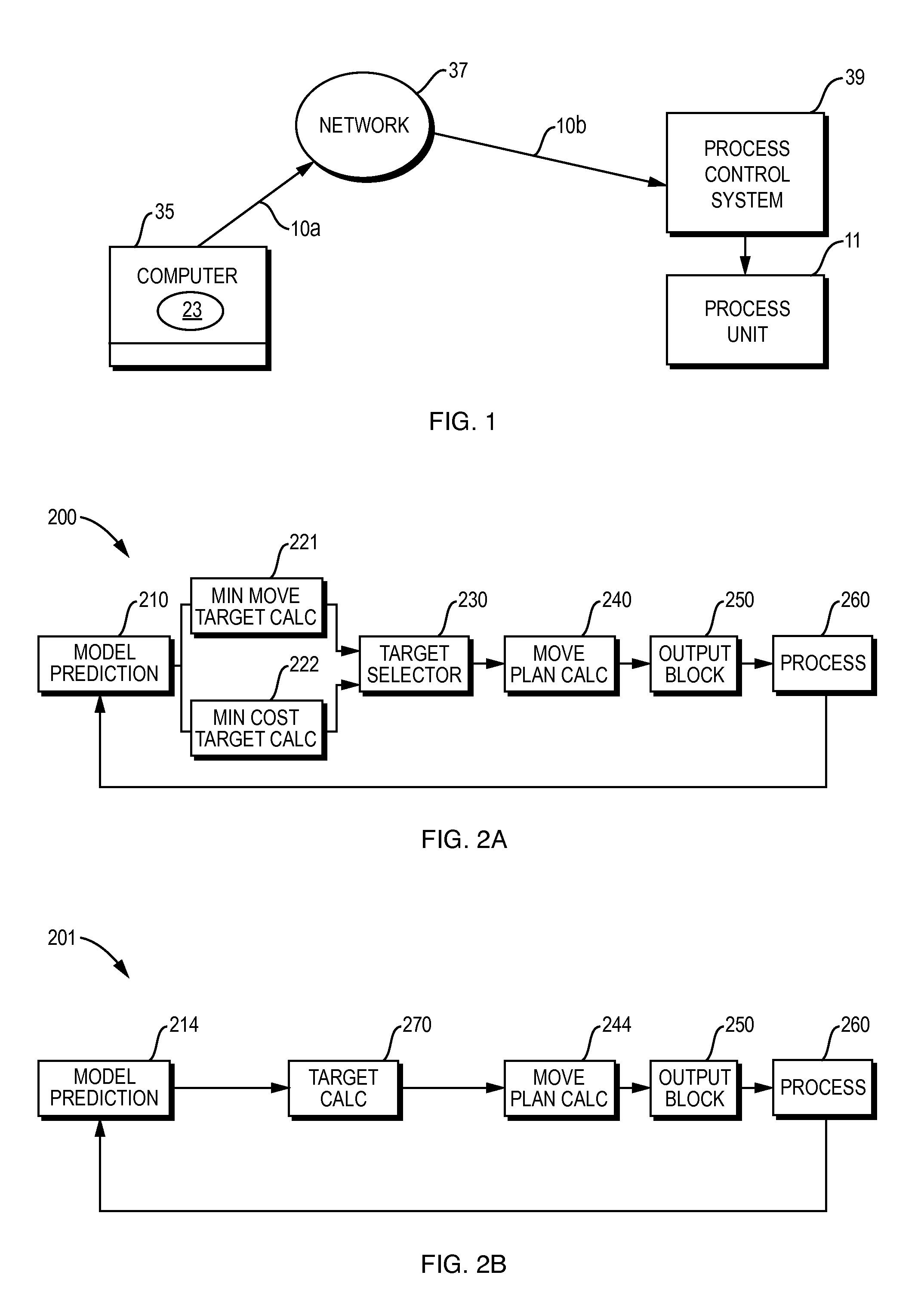
[0037]Illustrated in FIG. 1 is a multivariable process controller (or MPC controller) 23 embodying the present invention. In the preferred embodiment, the multivariable process controller 23 is implemented in software, hardware, or both executed on computer processing means 35. The computer processing means 35 is coupled in communication (for example, via a network 37) with process control system 39. The process control system 39 controls the subject process 11 using techniques and mechanics common in the art. The network 37 may be a local area network (LAN), a wide area network (LAN) and / or part of a global network (e.g., the Internet). Network 37 provides access to computer means 35 and process control system 39 across communication lines 10a and 10b and the like common in the art....


PUM


Abstract

An integrated multivariable predictive controller (MPC) and tester is disclosed. The invention system provides optimal control and step testing of a multivariable dynamic process using a small amplitude step for model identification purposes, without moving too far from optimal control targets. A tunable parameter specifies the trade-off between optimal process operation and minimum movement of process variables, establishing a middle ground between running a MPC on the Minimum Cost setting and the Minimum Move setting. Exploiting this middle ground, embodiments carry out low amplitude step testing near the optimal steady state solution, such that the data is suitable for modeling purposes. The new system decides when the MPC should run in optimization mode and when it can run in constrained step testing mode. The invention system determines when and how big the superimposed step testing signals can be, such that the temporary optimization give-away is constrained to an acceptable range.

Description

RELATED APPLICATION(S)[0001]This application claims the benefit of U.S. Provisional Application No. 61 / 596,459, filed on Feb. 8, 2012.[0002]The entire teachings of the above application(s) are incorporated herein by reference.BACKGROUND OF THE INVENTION[0003]Multivariable Predictive Control (MPC) is the most widely used advanced process control technology in process industries, with more than 5,000 worldwide applications currently in service. MPC, which is sometimes also referred to as multivariate control (MVC), relies on dynamic models of an underlying process, e.g., linear dynamic models obtained by system identification.[0004]A common and challenging problem is that MPC control performance degrades over time due to inevitable changes in the underlying subject process, such as equipment modifications, changes in operating strategy, feed composition changes, instrumentation degradation, etc. Such degradation of control performance results in loss of benefits. Among all possible ca...

Claims


Application Information

Patent Timeline
Patent Type & Authority Patents(United States)
IPC IPC(8): G05B13/02G05B13/04
CPCG05B13/022G05B13/048
Inventor ZHENG, QINGSHENG QUINNHARMSE, MAGIEL J.
Owner ASPENTECH CORP
Why Eureka
Eureka Blog
Learn More