Anchoring system

a technology of anchoring system and anchoring plate, which is applied in the direction of buildings, buildings, constructions, etc., can solve the problems of weakened holding strength of existing floors, damage to the integrity of foundations, and compromise of structural integrity of foundations, so as to improve the stability of anchoring plate, improve the dispersion and distribution, and improve the effect of anchoring strength

Active Publication Date: 2016-12-13
KUNDEL INDS
View PDF63 Cites 9 Cited by
  • Summary
  • Abstract
  • Description
  • Claims
  • Application Information

AI Technical Summary

Benefits of technology

[0009]Notably, one of the many advantages of the instant invention is the ability to engineer the hold strength by arranging the proper anchoring / fastening pattern using anchor plates (also referred to herein as “pods”). More specifically, the pull-pattern formed by the threaded fasteners can be expanded across a wider area in the foundation (i.e., both inside and outside the perimeter of the mounting plate). As a result, the turn-over force is better dispersed and distributed, and more force is needed for a failure to occur by fracture of the foundation.
[0010]Another advantage of the instant invention is that the turn-over pivot point of the mounting base at the foundation no longer has to be at the immediate perimeter of the mounting plate as in the prior art. Instead, the pivot point is extending out (i.e., beyond the perimeter of the mounting plate), thereby creating a wider holding area. Also, the break-away pattern of the threaded fasteners can be weaved in-and-out such that the fracture boundary of the foundation is extended and uneven. Therefore, more of the foundation has to fracture for there to be a failure.
[0011]With this invention, a designer can select the appropriate number of anchor plates for the best design to optimize the over-turn moment, pivot point, and break-away pattern of the pole or column. Also, with the instant anchoring system, the optimum design can be engineered so that a preferred minimum spacing between threaded fasteners can be maintained for the best strength (e.g., in most designs the spaced-distances between threaded fasteners is preferably at least 10× the common diameter of the fasteners).
[0012]Also, in most cases no two installation sites are exactly identical. The concrete foundation is old, the depth is different, and / or the concrete may or may not have reinforcement bar for enhanced strength and integrity. In summary, therefore, the anchoring system in the instant invention provides engineering options to structurally optimize the holding strength for the many different sites in the field, without having to lay new foundation. By uniquely designing the arrangement of the plurality of anchor plates using the appropriate anchoring / fastening pattern about the base of a mounting plate, the turn-over force needed to break-away the pole or column can be better engineered. For example, the turn-over force can be maximized for a jib crane or minimized for those occasions that the pole or column must be engineered to break-away easily such as for a sign or light pole along a freeway (i.e., in the preferred embodiment discussed infra, such arrangements can be engineered having different pod patterns such that the threaded fasteners are or are not within the preferred 10× the common fastener diameter).

Problems solved by technology

However, a large number of anchor bolts of the type typically used, can damage the integrity of the foundation.
Also, if the spacing of the anchor bolts is too close, the holding strength of the existing floor can be weakened.
Further yet, if the pull-out pattern is a continuous line or circle within the perimeter of the mounting base—e.g., one anchor bolt after the other like the plurality of perforations around the outside of a postage stamp used to enhance tearing—the structural integrity of the foundation can be compromised.
Also, the break-away pattern of the threaded fasteners can be weaved in-and-out such that the fracture boundary of the foundation is extended and uneven.
Therefore, more of the foundation has to fracture for there to be a failure.

Method used


Image

  • Anchoring system
  • Anchoring system
  • Anchoring system

Examples


Embodiment Construction

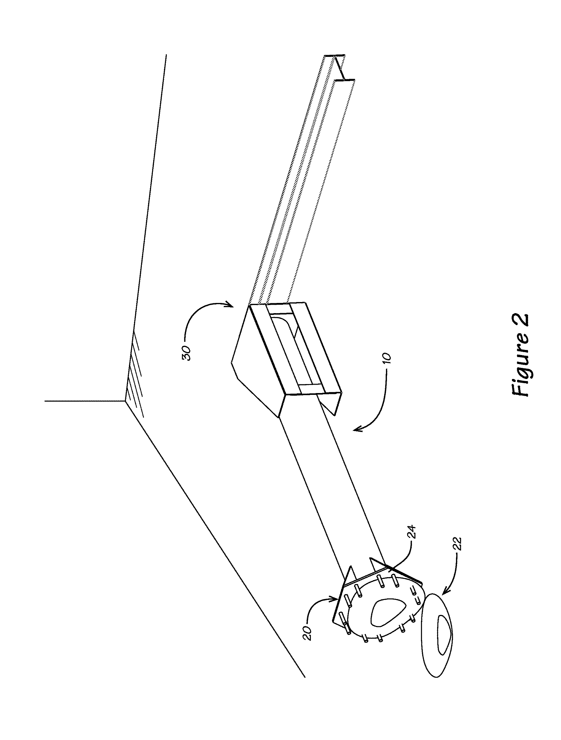
[0022]This description begins with reference to FIG. 2 and an explanation of the problem inherent therewith. The support systems used for poles or columns 10 in the prior art often include a mounting plate 24 extending perpendicular to the longitudinal axis of the pole or column 10. The mounting plate 24 provides peripheral openings 26 for receiving anchor bolts so that the pole 10 can be secured to the solid concrete foundation. If L-shaped bolts are not set in place when new concrete is poured, the alternative is to drill holes in an existing foundation 22 and attach the base thereto using concrete anchor bolts 120, such as concrete wedge-type anchor bolts known in the industry.

[0023]Moreover, holes are drilled in the concrete using a hammer drill and a carbide tip masonry drill bit, the same diameter as the anchor bolt 120. The concrete wedge anchor bolts 120 are then hammered into the drilled holes to ensure the desired depth after passing through mount openings 26 around the pe...


PUM


Abstract

An anchoring system to secure a mounting plate at a base of a pole or column to a concrete foundation includes a plurality of base plates. Each base plate has a planar surface, center-point, and plurality of fastener openings spaced about the center-point. A plurality of concrete anchoring fasteners having a common cross-sectional diameter secures each base plate to the foundation. An attachment bolt at the center-point of each base plate extends perpendicular to the planar surface for securing through an attachment bolt opening inside a peripheral edge of the mounting plate. The anchoring fasteners for securing the base plates to the foundation are spaced apart no less than ten times the common cross-sectional diameter.

Description

FIELD OF THE INVENTION[0001]This invention relates to an anchoring system for a pole or column to a hard surface such as a rock, concrete or like foundation, and wherein the system comprises a plurality of plates arranged about a base of the pole or column held by anchoring fasteners symmetrically aligned and disposed a predetermined distance for securing the same to the foundation.BACKGROUND[0002]This invention is in the field of an anchoring system for supporting an elongated member like a sign post, light pole or jib crane pillar in a solid foundation (such as a top and bottom supported jib crane and / or floor mounted pillar type that telescopes, or the like). Moreover, the invention in this case is directed to an anchoring system for providing a pole support as shown, for example, in U.S. Pat. No. 5,878,540.[0003]The supported pole or column is often mounted at a base having a mounting plate which extends perpendicularly to the longitudinal axis of the support pole or column to p...

Claims


Application Information

Patent Timeline
Patent Type & Authority Patents(United States)
IPC IPC(8): E04H12/22E04H12/34
CPCE04H12/2261E04H12/34B66C23/208B66C23/62E02D27/42
Inventor KUNDEL, SR., ROBERTKUNDEL, JR., ROBERTSCHLEY, RICHARD A.
Owner KUNDEL INDS
Why Eureka
Try Eureka