Thermal energy storage system comprising a combined heating and cooling machine and a method for using the thermal energy storage system

a technology of thermal energy storage and combined heating, which is applied in the direction of indirect heat exchangers, lighting and heating apparatus, heating types, etc., can solve the problems of grid order, surplus energy is kept unused, and the level of electricity production, so as to increase the coefficient of performance, increase the thermal capacity, and efficient and flexible thermal energy storage system

Inactive Publication Date: 2016-12-13
SKANSKA SVERIGE
View PDF217 Cites 12 Cited by
  • Summary
  • Abstract
  • Description
  • Claims
  • Application Information

AI Technical Summary

Benefits of technology

[0012]One advantage of the thermal energy storage system is the possibility of optimizing the storage of energy by choosing at which temperature levels the energy is to be retrieved and released, all depending on the specific conditions in the grid and in the energy storage at a given period in time. Other advantages are the utilization of surplus electrical energy in the grid and the possibility of easily balancing the production of electricity against the consumption of electrical energy.
[0014]Each heat pump may comprise at least two compressors, for facilitating an efficient and flexible thermal energy storage system to increase the thermal capacity and in combination with multiple heat pumps increase the coefficient of performance.
[0015]In one embodiment, the internal combined heating and cooling machine is adapted for alternating the connection between the at least two compressors between series connection and parallel connection, for allowing both an increase of storage capacity for heated and cooled fluid as well as an increase of the heating capacity of the storage. Another advantage is that the internal combined heating and cooling machine gives the possibility of optimizing the thermal storage by choosing at which temperature levels the energy is to be retrieved and released, all depending on the specific demands in the district heating and cooling systems and in the energy storage at a given period in time.
[0017]The thermal energy storage system may further comprise at least one immersion heater arranged within the energy storage, such that surplus electricity in the electrical grid can be efficiently transformed into thermal energy and directly in the thermal energy storage.
[0025]One advantage of the method of using the thermal energy storage system is the possibility of optimizing the storage of energy by choosing at which temperature levels the energy is to be retrieved and released, all depending on the specific conditions in the electrical grid and in the energy storage at a given period in time. Other advantages are the utilization of surplus electrical energy in the grid and the possibility of easily balancing the production of electricity against the consumption of electrical energy.

Problems solved by technology

If the deviation is too large, the grid is put out of order.
Waste simply means that surplus energy is kept unused, i.e. that an amount of the solar or wind power plants are shut down in order to reduce the level of electricity production.
This is however not always possible since there has to be a market to which one can export the electricity.
If the power supply in nearby countries, in the future, also develops into a similar wind and power supply, the possibilities for export will be limited.
Further, it is not possible to use all the generated electricity in the district heating system since the surplus production normally occurs during spring and summer at periods when the consumption is low, i.e. the production and the consumption is not balanced.
These situations may also be a result of the difficulties in predicting both the weather and the electricity consumption.

Method used


Image

  • Thermal energy storage system comprising a combined heating and cooling machine and a method for using the thermal energy storage system
  • Thermal energy storage system comprising a combined heating and cooling machine and a method for using the thermal energy storage system

Examples


Embodiment Construction

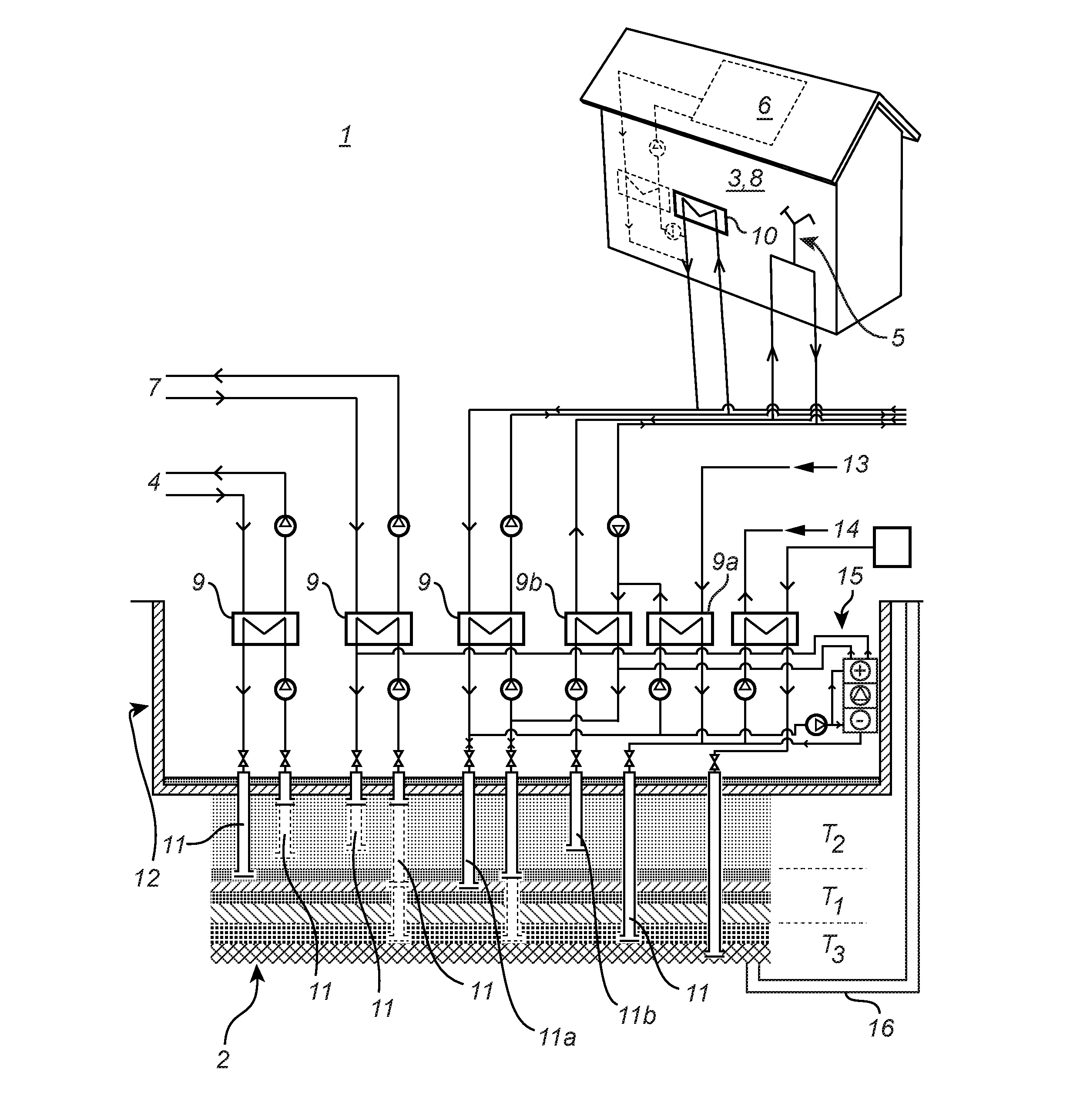
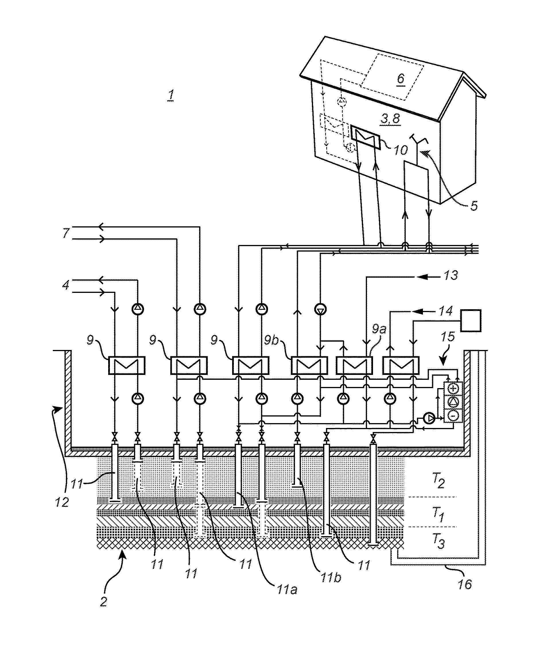
[0029]FIG. 1 illustrates an energy storage system according to a first embodiment of the invention. The system comprises an energy storage 2, which may be a tank, an underground cavern, or a thermal energy storage designed for high performance on input / output of energy and a large seasonal storage capacity.

[0030]In the energy storage 2, energy of different temperatures is stored. The upper layers of the energy storage have higher temperatures than the cooler, lower layers. There are also layers having intermediate temperatures in the transition zone there between. The temperatures within the layers of the energy storage can be defined as temperature intervals T1, T2, and T3. These intervals may be adapted to any specific working conditions. As a mere example, the first temperature interval T1 is within the range of 15° C. to 65° C., the second temperature interval T2 is within the range of 50° C. to 100° C., and the third temperature interval T3 is within the range of 4° C. to 25° C...


PUM


Abstract

The present invention relates to a thermal energy storage system comprising an energy storage (2) having a vertical temperature gradient and an internal combined heating and cooling machine (15). The internal combined heating and cooling machine (15) is adapted for retrieving energy having a first temperature from the energy storage, while simultaneously returning heated energy having a second higher temperature and cooled energy having a third lower temperature. The invention also relates to a method for using the thermal energy storage system.

Description

[0001]This application claims benefit from International Application No. PCT / SE2013 / 051283, which was filed on Nov. 1, 2013, which claims priority to Swedish Patent Application No. 1251241-4, which was filed Nov. 1, 2012, the entireties of said patent applications are incorporated herein by reference.FIELD OF THE INVENTION[0002]The present invention relates to a thermal energy storage system comprising an energy storage having a vertical temperature gradient and an internal combined heating and cooling machine.BACKGROUND OF THE INVENTION[0003]Electrical energy today is primarily supplied through turbine based electrical generation. The electricity supply to the electrical grid must constantly be balanced against the accumulated electrical consumption and any losses in the grid. When there is unbalance, the frequency of the grid is affected such that an overproduction leads to an increase in frequency and an underproduction leads to a decrease in frequency in relation to the standard...

Claims


Application Information

Patent Timeline
Patent Type & Authority Patents(United States)
IPC IPC(8): F28D20/00F24D19/10F24D3/08
CPCF28D20/0034F24D3/08F24D19/1066F28D20/0039F28D20/0052F24D2200/11F24D2200/123F28D2020/0069Y02B10/40Y02E60/142Y02P80/15Y02E60/14F24D11/02F24H4/04F28D20/0043
Inventor PILEBRO, HANSSTRAND, TOBIASVESTIN, RASMUS
Owner SKANSKA SVERIGE
Why Eureka
Try Eureka