
Ion detection

a mass analyzer and ion detection technology, applied in the field of mass analyzers, can solve the problems of limited m/z analysis in ftms, limited analytical performance, and inability to become widespread, and achieve the effects of improving the identification of mass spectra peaks, improving the mass spectrum, and increasing the speed

Active Publication Date: 2016-12-13
THERMO FISHER SCI BREMEN
View PDF17 Cites 2 Cited by
  • Summary
  • Abstract
  • Description
  • Claims
  • Application Information

AI Technical Summary

Benefits of technology

[0011]The use of a pulse detection electrode arrangement together with a harmonic detection electrode allows additional data to be obtained from the mass analyser. Advantageously, the harmonic transient signal and the pulse transient signal are obtained at substantially the same time. The combination of these two signals, which in the preferred embodiment are both image current signals, allows a range of different data processing techniques to be used. In fact, the pulse transient signal can beneficially be used to improve a spectral line list obtained using the harmonic transient signal.
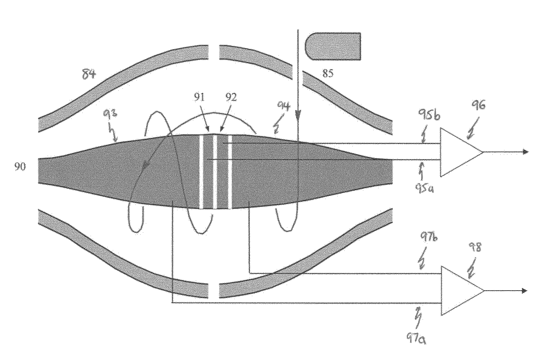
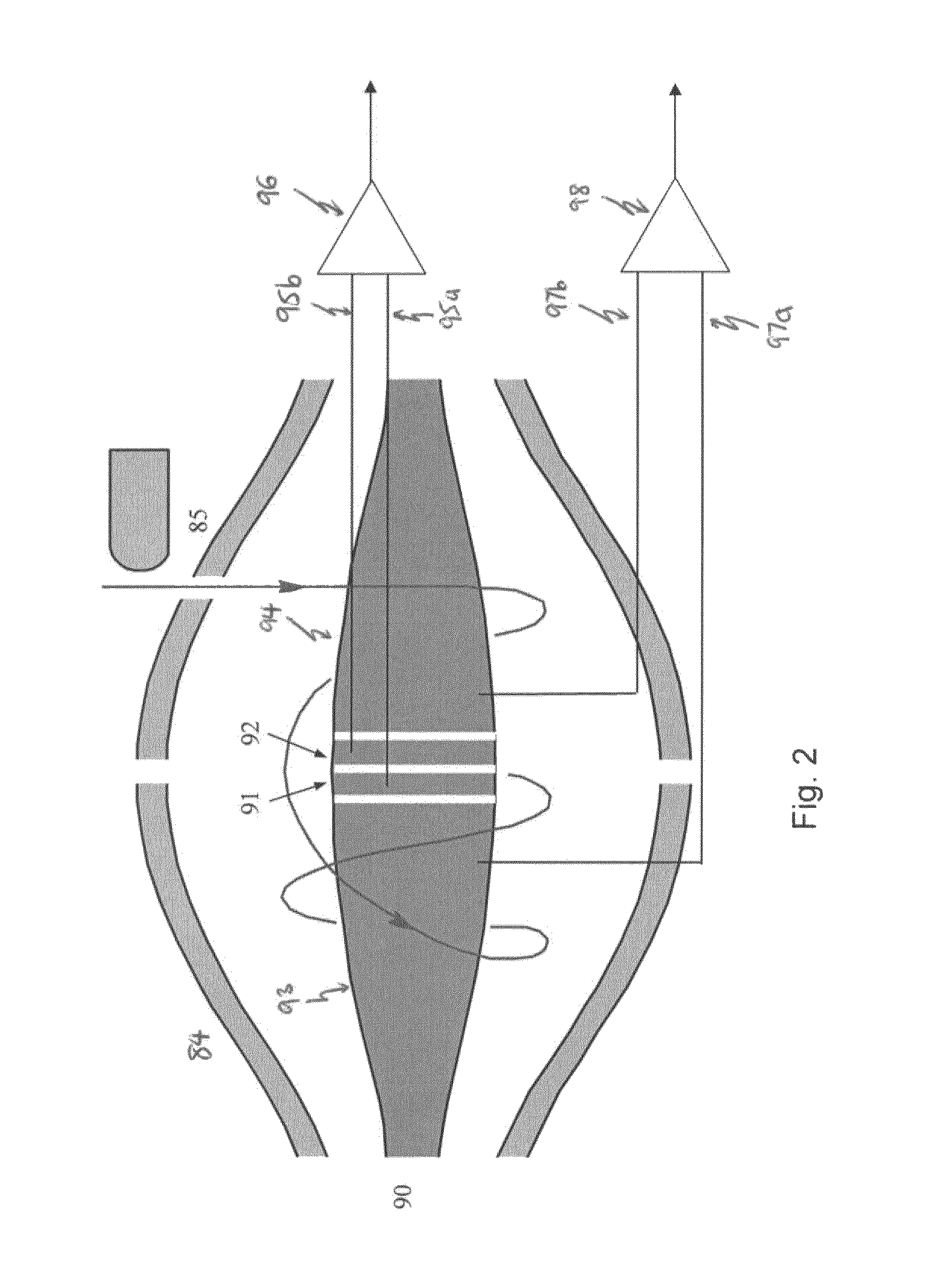
[0016]Beneficially, the pulse detection electrode arrangement comprises at least one detection electrode having a width in the longitudinal direction such that ion packets transit near the at least one detection electrode for a duration that is substantially shorter than the half-period of the ion packet oscillation. Preferably, the width is such that the duration of transit for the ion packets is no more than one of: 50%; 25; 12.5%; or 6.25% than the half-period of the ion packet oscillation. Adjusting the width of the electrode may allow a pulse transient signal to be detected, preferably an image current signal.
[0021]In embodiments, the central electrode portion may comprise a first central electrode part and a second central electrode part, the pulse transient signal comprising a combination of an image current generated in the first central electrode part and an image current generated in the second central electrode part. Beneficially, this allows common mode noise to be rejected, by combining two pulse transient image currents.
[0031]In some embodiments, the step of identifying ion intensity with respect to mass-to-charge ratio further comprises: processing the pulse transient signal to identify a preliminary set of frequencies and associated intensities; and processing the harmonic transient signal together with the preliminary set of frequencies and associated intensities to determine ion intensity with respect to mass-to-charge ratio. This allows improved identification of mass spectra peaks at higher speeds than existing systems, due to the processing of the pulse transient signal in parallel with the harmonic transient signal and using the two signals in combination to provide an improved mass spectrum.

Problems solved by technology

FTMS using RF fields are also known, but did not become widespread due to limited analytical performance.
It is known that the resolving power of m / z analysis in FTMS is limited by the Fourier Transform uncertainty principle.
Frequently, liquid separation is performed before mass analysis and the increasing speed of such separation is putting pressure on the detection time in mass spectrometry and tandem mass spectrometry analysis.
Reducing detection time without significantly affecting resolving power is a major challenge in FTMS.
This is known as the harmonic inversion problem and is a difficult non-linear fitting problem, especially for a large number of noisy peaks typical for mass spectrometry.
Noisy data impedes the construction of a list of peaks or spectral lines from the harmonic transient using these alternatives to Fourier Transforms.

Method used


Image

  • Ion detection
  • Ion detection
  • Ion detection

Examples


first embodiment

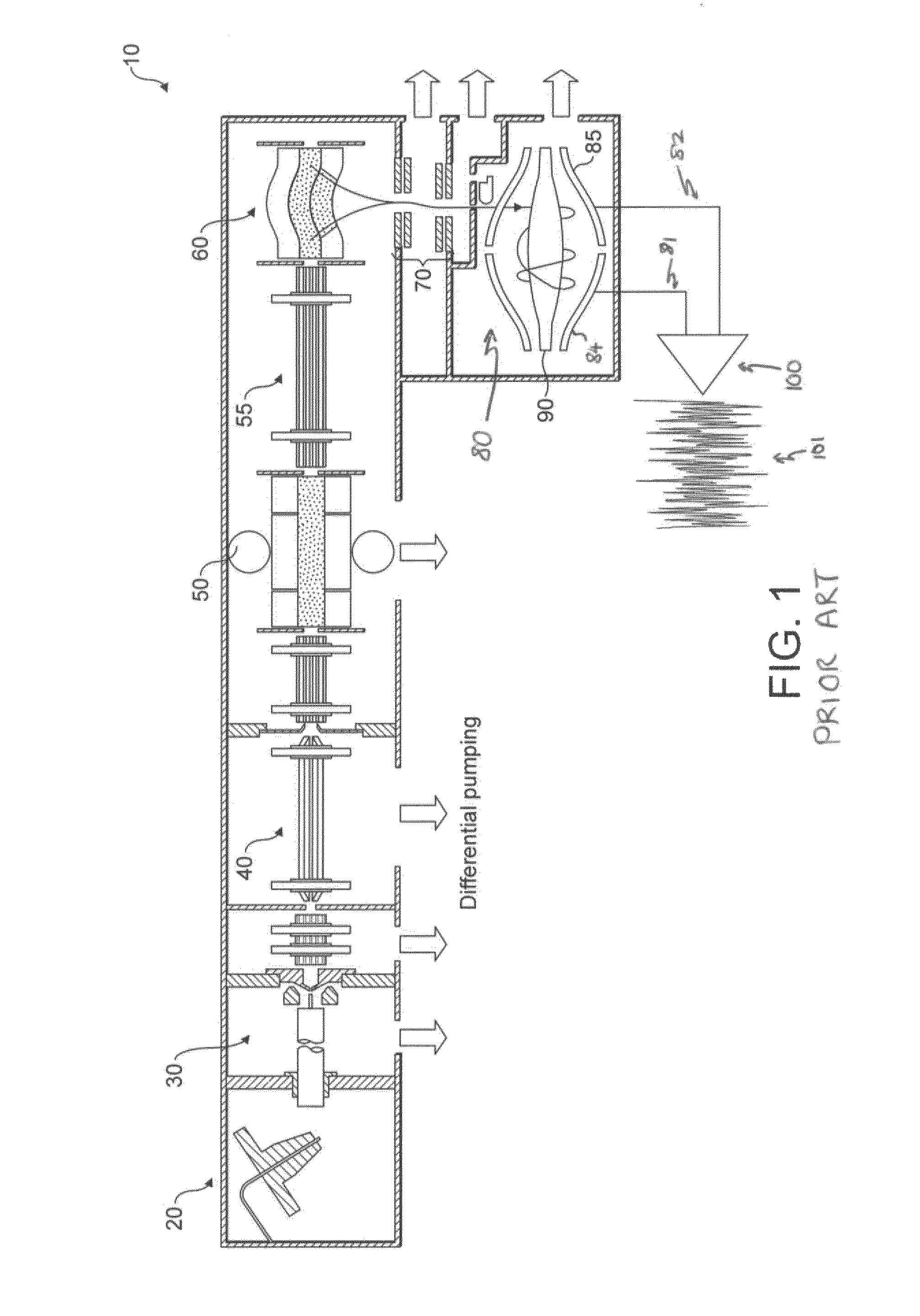
[0053]Referring next to FIG. 2, an electrostatic trap according to the present invention is shown. Where the same components to those identified in FIG. 1 are shown, identical reference numerals are used.

[0054]Central electrode 90 is formed in such a way that a first detection strip electrode 91 and a second detection strip electrode 92 are near the centre of the electrode. A first side electrode 93 and a second side electrode 94 are also formed in this way. The first strip electrode 91 and the second strip electrode 92 are near the centre of the central electrode 90 (z=0), such that they are closest to the beam. The beam has a cylindrical envelope as in existing instruments.

[0055]After ions are injected through the injection slot of the electrostatic trap analyser and brought closer to the central electrode 90 by ramping the voltage between centre electrode 90 and outer electrodes 84 and 85, the ions move on a stable circular spiral trajectories at a desired radius. If the central ...

second embodiment

[0082]Referring now to FIG. 6, an electrostatic trap according to the present invention is shown. This embodiment functions according to similar principles as the embodiment shown in FIG. 2. However in this case, pulse detection is performed with the help of secondary electron detection. A conversion electrode 140 is mounted on the central electrode 90 and a grid electrode 150, dynode 160 and microchannel plates 170 are also provided.

[0083]Firstly, conventional image current detection is performed with ions moving at a considerable distance from a conversion electrode 100. In this way, the harmonic transient image current is obtained. Subsequently, the voltage on the central electrode 90 is ramped slightly so that ions start to move on trajectories that intersect with the conversion electrode 140. This electrode has a different voltage to that applied to the central electrode 90, so that the equipotentials within the electrostatic trap 80 are not perturbed.

[0084]On each pass, a port...


PUM


Abstract

Mass analyzers and methods of ion detection for a mass analyzer are provided. An electrostatic field generator provides an electrostatic field causing ion packets to oscillate along a direction. A pulse transient signal is detected over a time duration that is significantly shorter than a period of the ion oscillation or using pulse detection electrodes having a width that is significantly smaller than a span of ion harmonic motion. A harmonic transient signal is also detected. Ion intensity with respect to mass-to-charge ratio is then identified based on the pulse transient signal and the harmonic transient signal.

Description

TECHNICAL FIELD OF THE INVENTION[0001]The present invention relates to a mass analyser or a method of ion detection for a mass analyser.BACKGROUND TO THE INVENTION[0002]Fourier Transform Mass Spectrometry (FTMS) uses an electromagnetic field in which coherent packets of ions undergo free harmonic oscillations within the analyser with a period that is a function of their mass to charge (m / z) ratio. The electromagnetic field can be provided by the combination of an electrostatic field and a magnetostatic field, for example in a Fourier Transform Ion Cyclotron Resonance (FTICR) mass analyser, or by an electrostatic field only, for example in an orbital trapping mass analyser (marketed under the name Orbitrap™). FTMS using RF fields are also known, but did not become widespread due to limited analytical performance.[0003]Typically, ions are detected by an image current generated in detection electrodes as the ions pass nearby. It is known that the resolving power of m / z analysis in FTMS...

Claims


Application Information

Patent Timeline
Patent Type & Authority Patents(United States)
IPC IPC(8): H01J49/00H01J49/42H01J49/38H01J49/02H01J49/28
CPCH01J49/282H01J49/027H01J49/38H01J49/4245H01J49/425H01J49/0027H01J49/08
Inventor MAKAROV, ALEXANDER A.
Owner THERMO FISHER SCI BREMEN
Learn More