Muffler for an exhaust system of an internal combustion engine

a technology of internal combustion engine and exhaust system, which is applied in the direction of gas passages, gas chambers, and sliding devices, can solve the problems of bending of the baffle plate, ticking and pinging noise, and the downward bent of the baffle lip tips, so as to reduce noise, improve the damping of vibration in the muffler, and improve the effect of conta

Active Publication Date: 2017-01-03
BOSAL EMISSION CONTROL SYST
View PDF14 Cites 1 Cited by
  • Summary
  • Abstract
  • Description
  • Claims
  • Application Information

AI Technical Summary

Benefits of technology

[0020]Still in accordance with a further aspect of the invention, the length of the contact portion of the baffle lip is reduced with increasing curvature angle of the inwardly curved end portion.
[0036]The geometry of the end of the baffle lip according to the present invention avoids gripping of the baffle into the inner wall of the housing of the muffler and improves the sliding contact between the baffles and the shell of the muffler housing. The static friction force is reduced, thereby reducing the stick-slip phenomenon when the baffle is brought under tension to eventually start sliding during the stuffing process or during heating up and cooling down of the muffler at lower forces applied on the baffle. The reduced tension reduces the forces applied to the baffle and therefore reduces the risk of bending the baffle. Additionally, the geometry of the baffle lip according to the present invention allows the introduction of the baffle into the housing of the muffler in either direction during stuffing process. Furthermore, the curved end portion of the baffle lip increases the stiffness of the baffle.
[0037]The varying geometries of the baffle lip allows for fine-tuning of the properties of the baffle, for example regarding the stiffness of the baffle plate, and at the same time reducing the amount of material needed (metal sheet) for forming such optimized baffle. This optimization additionally has a beneficial impact on the weight of the muffler, in which these baffles are arranged, further contributing to the manufacture of light weight mufflers.
[0038]The curvature angle of the inwardly curved end portion along the circumference of the baffle plate may be varied where necessary for optimal stiffness and reduced weight of the baffle.
[0039]The curvature angle of the inwardly curved end portion along the circumference of the baffle plate may be varied while reducing or increasing the length of the contact portion depending on the contact pressure of the muffler shell on the baffle leading to the necessity of a certain length of the contact portion for compensation of the applied contact pressure. For example, the contact pressure of the muffler shell on the baffle generally is higher at the corners of the muffler, where the muffler shell has a smaller contact portion bending radius, than at the flat intermediate portions between the corners of the muffler, where the muffler shell has a larger contact portion bending radius than at the corners. Therefore, the optimization of the length of the contact portion simultaneously with the curvature angle of the inwardly curved end portion of the baffle lip allows for compensating the contact pressure (bending stress) around the circumference of the baffle plate while enhancing the stiffness of the baffle with reduced weight.
[0041]By the use of several metal sheets for the baffle, the friction between the metal sheets additionally increases the damping of vibrations in the muffler. The present invention also allows the use of baffles whose baffle lip has no contact portion with the inner wall of the shell. In general, the present invention presents the advantage of maintaining good contact between baffle and housing, reducing noise due to sliding and enhances mechanical durability of the muffler, allowing the usage of thinner thicknesses t of the baffles.

Problems solved by technology

Second, the baffles support the pipes.
The afore-described outwardly bent baffle lip tips also have a negative impact on the “stick and slip” movement of the baffle.
The stick and slip movement of the baffle typically occurs during the heat-up of the muffler during operation, or the cooling down of the muffler after operation and generates the well-known “tick and ping” noise.
The frictional forces may result in bending of the baffle plate.
Accordingly, reduction of the wall thickness of the baffle (and an associated saving of weight) is very limited only, since a further reduction of the wall thickness of the baffle would increase the tendency of the baffle plate to bend due to reduced stiffness of the baffle plate which may create problems regarding the stuffing of the baffle plate into the muffler shell during assembly of the muffler and which may also create loss of the function of the muffler due to thermal cycling.

Method used


Image

  • Muffler for an exhaust system of an internal combustion engine
  • Muffler for an exhaust system of an internal combustion engine
  • Muffler for an exhaust system of an internal combustion engine

Examples


Embodiment Construction

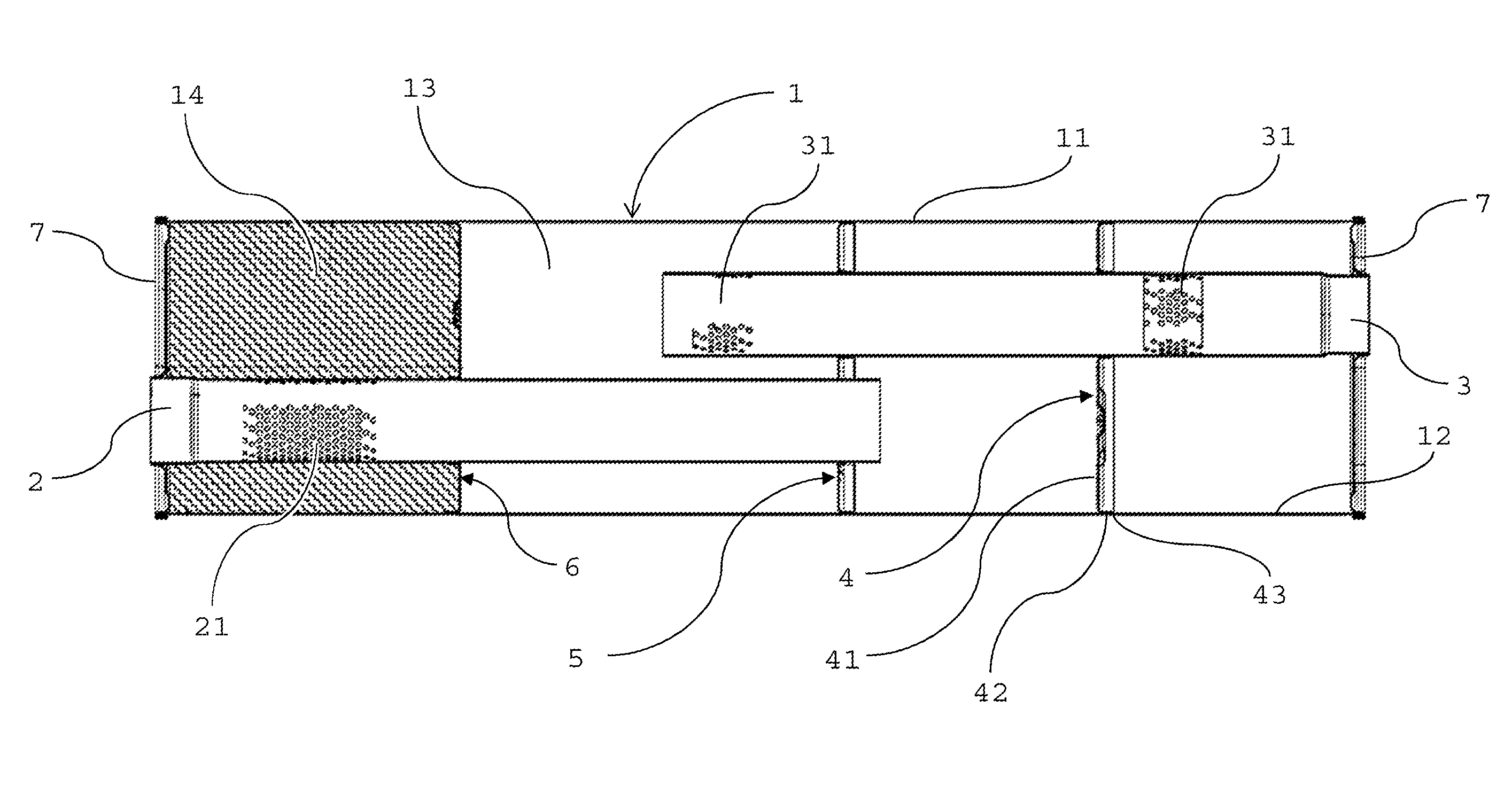
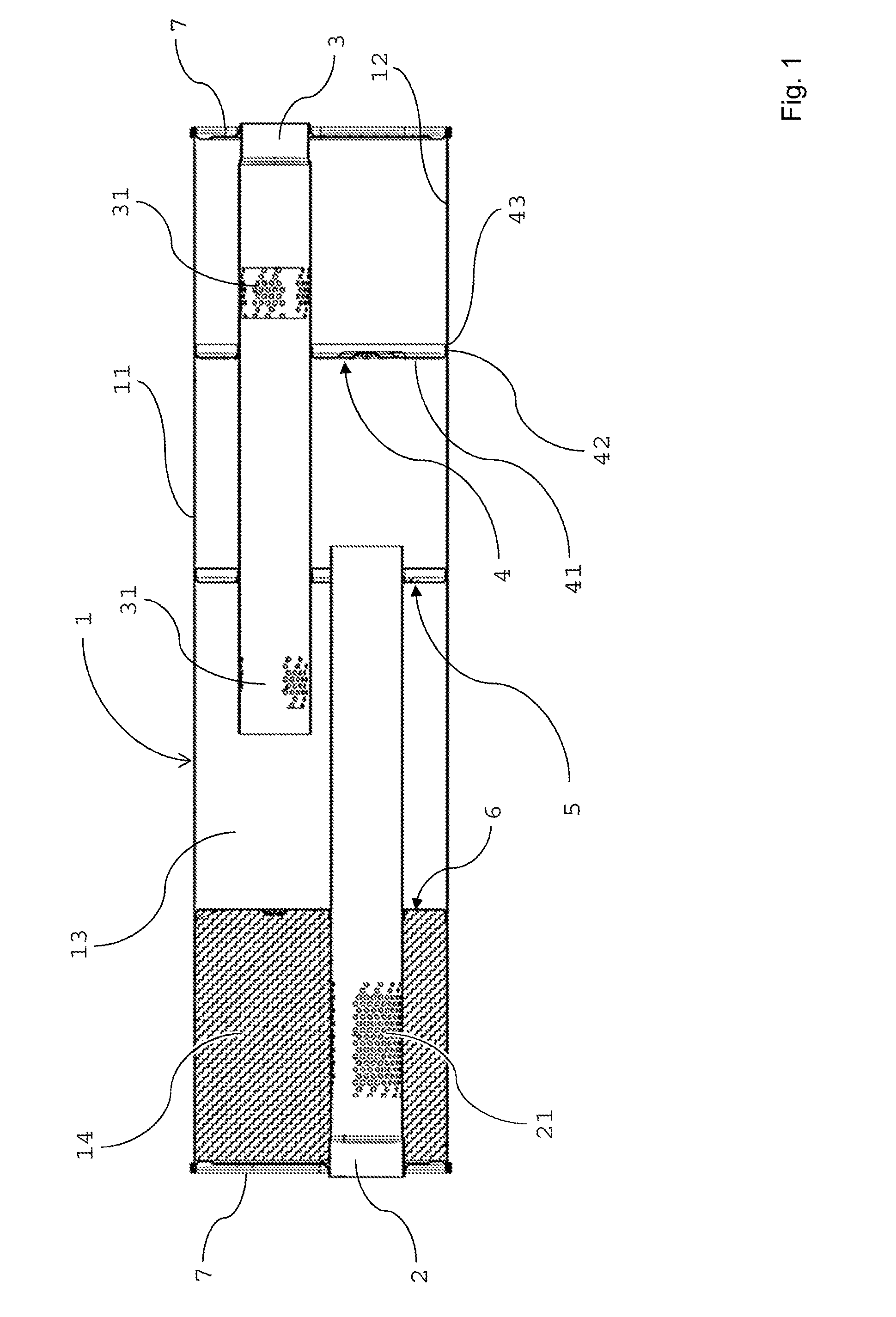
[0058]As shown in FIG. 1, a muffler includes a housing 1 comprising a shell 11 having an inner wall 12 and receiving an inlet pipe 2 and an outlet pipe 3 both extending into an inner space formed by the housing 1. An inner space 13 is delimited by the shell 11 and by end-caps 7 of the housing. The end-caps 7 seal the housing 1 and generally comprise an orifice for receiving the inlet pipe 2 and / or the outlet pipe 3.

[0059]The inlet pipe 2 conveys exhaust gas stream from an exhaust of an internal combustion engine into the inner space 13 of the housing 1 and the outlet pipe 3 conveys the exhaust gas stream out of the inner space 13 of the housing 1.

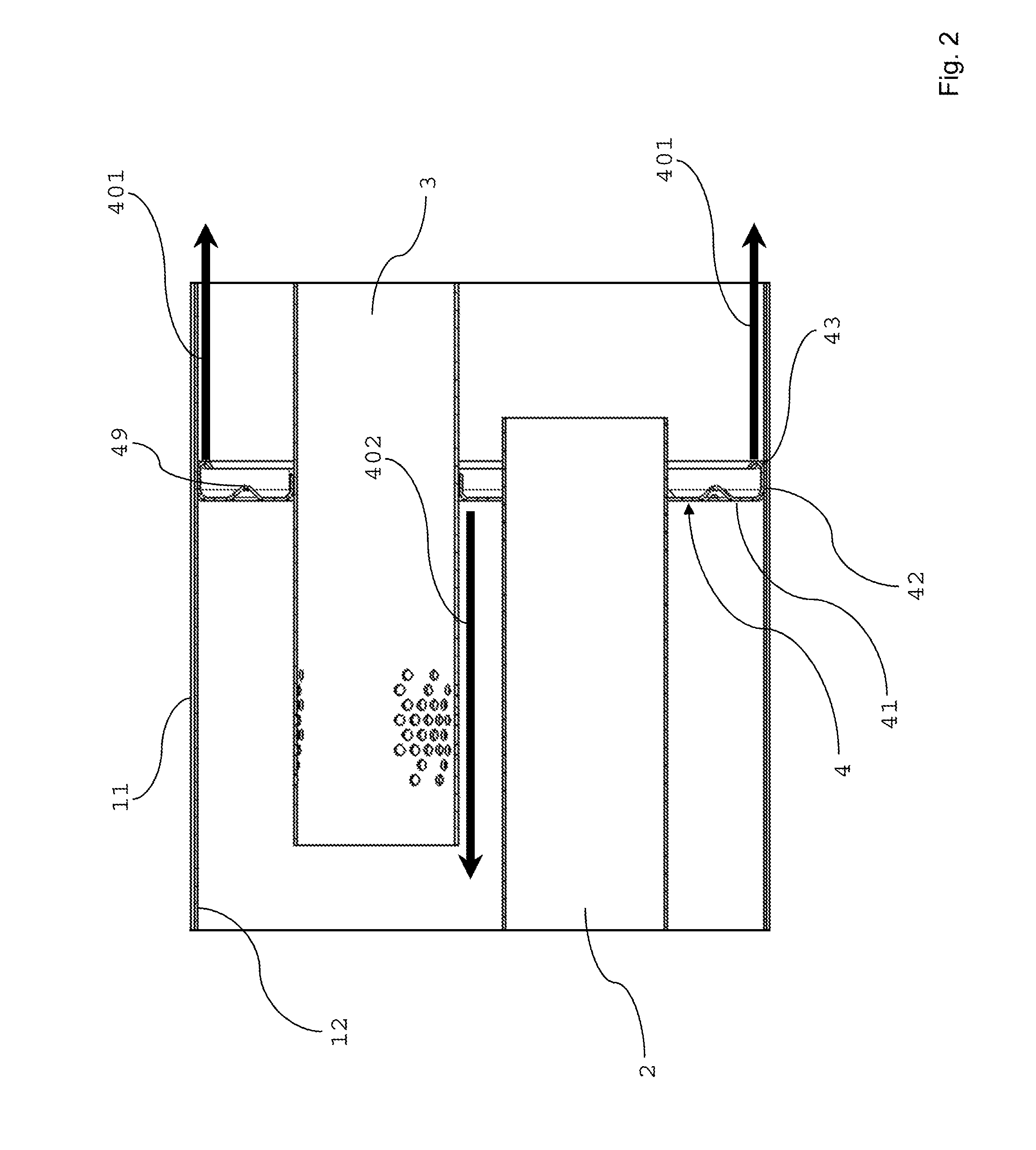
[0060]As shown in FIG. 1, the muffler has three baffles 4, 5, 6 arranged at a defined distance from each other inside the housing 1 in the inner space 13 of the muffler. The baffle plates 4, 5, 6 each comprise a baffle plate and a baffle lip arranged at the circumference of the respective baffle plate, which will be explained in the followi...


PUM


Abstract

A muffler for an exhaust system of an internal combustion engine, comprises a housing comprising a shell having an inner wall, an inlet pipe and an outlet pipe, the inlet pipe and the outlet pipe extending into an inner space of the housing, for conveying an exhaust gas stream into and out of the inner space of the housing, at least one baffle arranged in the inner space of the housing, the baffle comprising a baffle plate, the baffle plate having a circumference, and a baffle lip arranged at the circumference of the baffle plate, the baffle lip engaging the inner wall of the shell and having an end portion, wherein the end portion of the baffle lip is curved inwardly away from the inner wall of the shell.

Description

[0001]This application claims benefit of Serial No. 15160260.4, filed on 23 Mar. 2015 in the European Patent Office and which application is incorporated herein by reference. To the extent appropriate, a claim of priority is made to the above disclosed application.FIELD OF THE INVENTION[0002]The invention relates to a muffler for an exhaust system of an internal combustion engine.BACKGROUND[0003]Mufflers are used, for example, as components of exhaust systems of motor vehicles in general, and in particular as components of exhausts systems of cars. The muffler is designed to reduce the noise levels generated by the internal combustion engine. To this end, the acoustical waves propagate through a series of resonating chambers tuned to attenuate the noise. Alternatively or in addition, fibrous material may be arranged in one or more chambers of the muffler to attenuate the loudness of the sound pressure. The chambers within the muffler are formed by sectional plates called baffles whi...

Claims


Application Information

Patent Timeline
Patent Type & Authority Patents(United States)
IPC IPC(8): F01N1/08
CPCF01N1/083F01N13/007F01N1/003F01N1/006F01N1/084F01N1/10F01N2470/02F01N2470/18F01N2490/06F01N2490/08
Inventor GOMMANS, LEO
Owner BOSAL EMISSION CONTROL SYST
Why Eureka
Try Eureka