
Composite structure and raft for gas turbine engine

a gas turbine engine and composite structure technology, applied in the direction of machines/engines, efficient propulsion technologies, mechanical apparatuses, etc., can solve the problems of compromising the design of the aircraft, affecting the performance of the engine, and the bulky structure of the conventional harness itsel

Active Publication Date: 2017-01-03
ROLLS ROYCE PLC
View PDF10 Cites 4 Cited by
  • Summary
  • Abstract
  • Description
  • Claims
  • Application Information

AI Technical Summary

Benefits of technology

This patent describes a new way to transmit electrical signals in composite materials, such as those used in gas turbine engines. By using the reinforcing fibers in the material to transmit signals, separate signal transmission arrangements may not be necessary. The structure also allows for easy addition or modification of electrical units. This new system is more robust and has no single point of potential failure. The patent also describes how this technology can be used in the design of gas turbine engines, providing greater protection and easier maintenance compared to conventional harnesses. Overall, this patent describes a method to incorporate electrical functionality into composite materials, which can be useful in modern aircraft.

Problems solved by technology

This makes the conventional harness itself bulky, heavy and difficult to manipulate.
The conventional harnesses occupy significant space within a gas turbine engine (for example within the nacelle of a gas turbine engine), and thus may compromise the design of the aircraft, for example the size and / or weight and / or shape of the nacelle.
This can make the assembly process complicated (and thus susceptible to errors) and / or time consuming.
Disassembly of the conventional harnesses (for example removal of the conventional harnesses from a gas turbine engine during maintenance) may also be complicated and / or time consuming.
Thus, in many maintenance (or repair or overhaul) procedures on a gas turbine engine, removal and subsequent refitting of the conventional electrical harness may account for a very significant portion of the operation time and / or account for a significant proportion of the potential assembly errors.
The electrical conductors in the conventional harnesses may be susceptible to mechanical damage.
For example, mechanical damage may occur during installation (for example through accidental piercing of the protective sleeves / braiding) and / or during service (for example due to vibration).
In order to reduce the likelihood of damage to the conductors in a conventional harness, the protective sleeves / braiding may need to be further reinforced, adding still further weight and reducing the ease with which they can be manipulated.
Similarly, the exposed electrical connectors used to connect one conductor to another conductor or conductors to electrical units may be susceptible to damage and / or may add significant weight to the engine.
Disassembly of a conventional harnesses can be complicated and / or time consuming.
Further, the electrical conductors in a conventional harness may be susceptible to mechanical damage.
In addition, the use of such rafts may significantly reduce the build and maintenance times of an engine, and / or reduce the possibility of errors occurring during such procedures.

Method used


Image

  • Composite structure and raft for gas turbine engine
  • Composite structure and raft for gas turbine engine
  • Composite structure and raft for gas turbine engine

Examples


Embodiment Construction

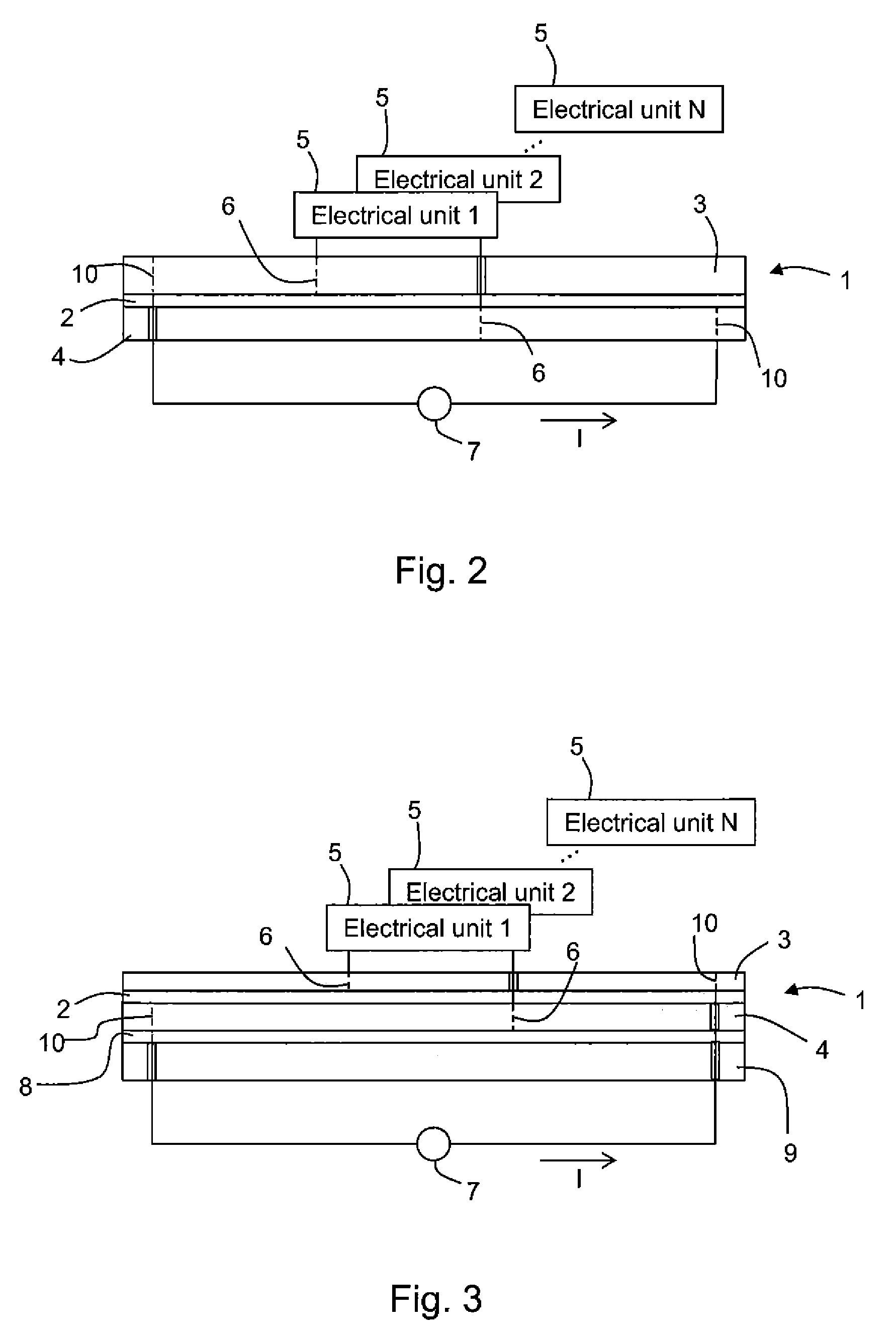
[0041]FIG. 2 shows schematically a side view of a panel 1 formed of rigid composite material. The panel may part of a vehicle. The primary function of the panel may be mechanical (for example structural) and / or aerodynamic. The panel may thus be an internal or external panel, i.e. it may or may not be exposed to external airflow in use.

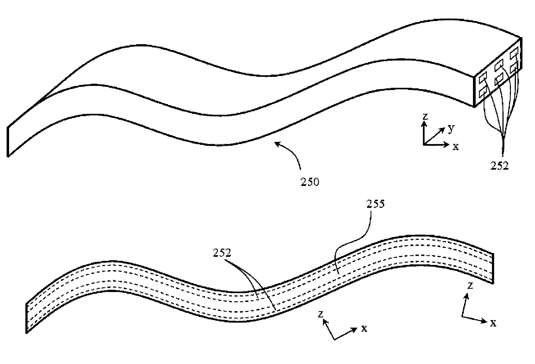
[0042]The composite material has a polymer matrix reinforced by non-metallic, but electrically conductive, continuous fibres, such as carbon fibres. The panel is divided into an upper portion 3 and a lower portion 4, the two portions being electrically isolated from each other by a barrier layer 2. The barrier layer may contain insulating continuous reinforcing fibres, such as glass fibres. The upper and lower portions can, therefore, be held at different electrical potentials.

[0043]One or more electrical units 5 each have electrodes 6 by which the units electrically bridge the upper 3 and lower 4 portions, the electrodes 6 connecting to the continuou...


PUM

PropertyMeasurementUnit
electrically conductiveaaaaaaaaaa
electrical potentialaaaaaaaaaa
poweraaaaaaaaaa

Abstract

A composite structure is provided. The structure is formed of rigid composite material in which non-metallic continuous fibers reinforce a polymer matrix. The continuous fibers are electrically conductive. The structure has electrodes electrically connected to the continuous fibers. The composite material contains one or more insulating barriers which electrically divide the structure so that a first portion of the material in electrical contact with one of the electrodes can be held at a different electrical potential to a second portion of the material in electrical contact with the other electrode. In use, an electrical unit can be provided to electrically bridge the first and second portions of the material such that electrical signals can be transmitted between the electrodes and the electrical unit via the continuous fibers.

Description

CROSS-REFERENCE TO RELATED APPLICATIONS[0001]This application is based upon and claims the benefit of priority from British Patent Application Number 1308021.3 filed 3 May 2013, the entire contents of which is incorporated by reference.BACKGROUND OF THE INVENTION[0002]1. Field of the Disclosure[0003]The present invention relates to a composite structure which can be used to transmit electrical signals.[0004]2. Description of the Related Art[0005]A typical gas turbine engine has a substantial number of electrical components which serve, for example, to sense operating parameters of the engine and / or to control actuators which operate devices in the engine. Such devices may, for example, control fuel flow, variable vanes and air bleed valves. The actuators may themselves be electrically powered, although some may be pneumatically or hydraulically powered, but controlled by electrical signals.[0006]Electrical power, and signals to and from the individual electrical components, is commo...

Claims


Application Information

Patent Timeline
Patent Type & Authority Patents(United States)
IPC IPC(8): H05K1/02F02C7/00F01D5/28C08K7/06C08K3/04F01D17/24F01D25/24
CPCH05K1/0298C08K3/04C08K7/06F01D5/282F01D17/24F01D25/24F02C7/00F05D2300/224F05D2300/50F05D2300/603F05D2300/6012F05D2300/614H05K2201/09218Y02T50/672Y02T50/673Y02T50/60
Inventor ZIZZO, CLAUDIO
Owner ROLLS ROYCE PLC
Learn More