Supercharge Your Innovation With Domain-Expert AI Agents!

Structure vibration control device

a technology of vibration control device and structure, which is applied in the direction of shock absorption device, building repair, and shock absorption device, etc., can solve the problems of deteriorating the function of the hydraulic damper

Active Publication Date: 2017-01-10
CHIHIRO SANGYO
View PDF52 Cites 9 Cited by
  • Summary
  • Abstract
  • Description
  • Claims
  • Application Information

AI Technical Summary

Benefits of technology

The device effectively suppresses structure vibrations by varying damping force characteristics in response to earthquake magnitude and temperature changes, maintaining functionality over time and reducing the risk of damage from seismic activity.

Problems solved by technology

Then, there is a possibility of leaking the oil out of the hydraulic chamber and of permitting outside air to enter the hydraulic chamber, thus quickly deteriorating functions of the hydraulic damper.

Method used


Image

  • Structure vibration control device
  • Structure vibration control device
  • Structure vibration control device

Examples


modified embodiment

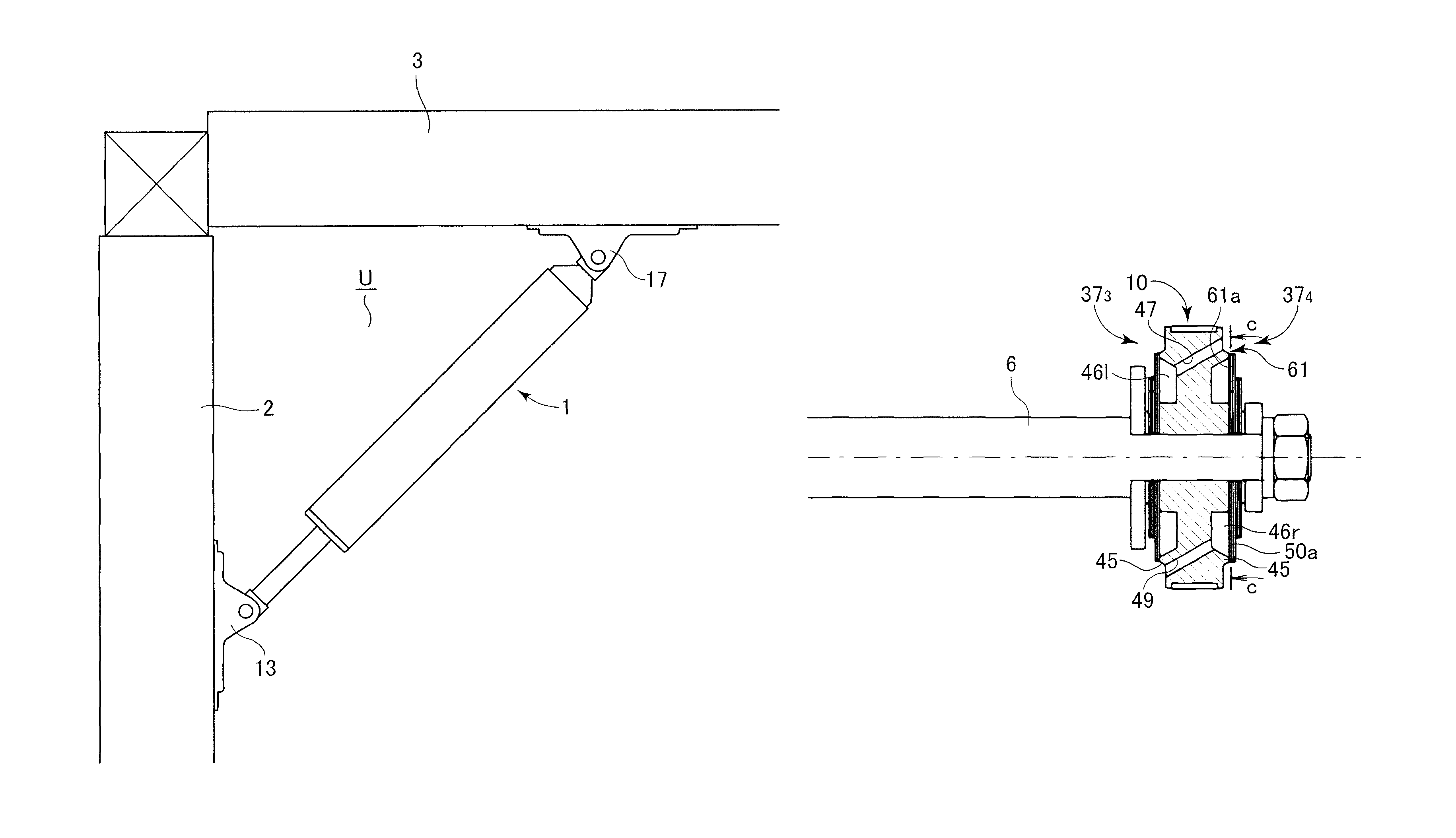
[0051]A partly modified embodiment will be described with reference to FIGS. 6A through 6C. It is noted that while the modified embodiment is different in that an orifice is added to the first and second piston valves beside the check valve function, the other components are the same with those described in the previous embodiment, so that the modified embodiment will be described by denoting by the same reference numerals and their explanation will be omitted here.

[0052]Each of the first and second piston valves 373 and 374 of the present embodiment has a check valve 60 composed of the plurality of valve seat plates 50, the disc spring 51 and the annular projection 45. Either one of the first and second piston valves 373 and 374, e.g., the second piston valve 374, is provided with the orifice (by-pass) 61 formed of one groove 61a extending from an outer diameter side of one sheet (50a) of the valve seat plates 50 to a position in contact with the hydraulic space 46 of the valve sea...


PUM


Abstract

A structure vibration control device includes a hydraulic damper having damping force characteristics that vary in response to a magnitude of an earthquake and having characteristics that are maintained for a long period of time regardless of an environmental temperature change. The hydraulic damper includes a preload chamber into which a high-pressure gas is charged in series with a hydraulic chamber. The preload chamber absorbs a volume change of the hydraulic chamber caused by the environmental temperature change and a piston rod and balances a bias force of a spring within the hydraulic chamber and of the preload chamber. Piston valves have high damping force characteristics against a weak earthquake and low damping force characteristics against a strong earthquake. The piston valves may include an orifice beside a check valve function, by which the high damping force characteristics lie within a range of 150 to 800 kN / (m / sec).

Description

CROSS-REFERENCE TO RELATED APPLICATIONS[0001]This application claims the benefit of Japanese Patent Application No. 2014-029673, filed on Feb. 19, 2014, and Japanese Application No. 2014-223389, filed on Oct. 31, 2014. These applications are hereby incorporated by reference herein in their entirety.BACKGROUND OF THE INVENTION[0002]Field of the Invention[0003]The present invention relates to a vibration control device attached aslant between two structural members such as a pillar and a beam of a structure to suppress vibrations of the structure when an earthquake hits.[0004]Description of the Related Art[0005]Hitherto, there is known a structure vibration control device using a hydraulic damper as disclosed in Japanese Patent Application Nos. H06-346625, H10-227145, and 2000-54677, for example. The hydraulic damper described above includes a cylinder configured such that a hydraulic chamber formed therein is partitioned by a piston into oil chambers and a piston rod is inserted thro...

Claims


Application Information

Patent Timeline
Patent Type & Authority Patents(United States)
IPC IPC(8): E04B1/98F16F9/19F16F13/00F16F9/06F16F15/02
CPCE04B1/98F16F9/061F16F9/19F16F13/007F16F15/022E04H9/027E04H9/024F16F9/3481E04G23/0218E04H9/0235E04H9/0237
Inventor UENO, HIROSHI
Owner CHIHIRO SANGYO
Features
  • R&D
  • Intellectual Property
  • Life Sciences
  • Materials
  • Tech Scout
  • Unparalleled Data Quality
  • Higher Quality Content
  • 60% Fewer Hallucinations
Learn More