Cryogenic air separation method and system

a separation method and air technology, applied in the field of cryogenic air separation methods and systems, can solve problems such as large shaft power

Active Publication Date: 2017-01-17
8 RIVERS CAPTTAL LLC
View PDF43 Cites 18 Cited by
  • Summary
  • Abstract
  • Description
  • Claims
  • Application Information

AI Technical Summary

Problems solved by technology

The cooling process and the separation of the air components typically requires a large amount of shaft power to drive the air compressors used in the refrigeration and separation cycles.

Method used


Image

  • Cryogenic air separation method and system
  • Cryogenic air separation method and system

Examples


Embodiment Construction

[0073]The invention now will be described more fully hereinafter through reference to various embodiments. These embodiments are provided so that this disclosure will be thorough and complete, and will fully convey the scope of the invention to those skilled in the art. Indeed, the invention may be embodied in many different forms and should not be construed as limited to the embodiments set forth herein; rather, these embodiments are provided so that this disclosure will satisfy applicable legal requirements. As used in the specification, and in the appended claims, the singular forms “a”, “an”, “the”, include plural referents unless the context clearly dictates otherwise.

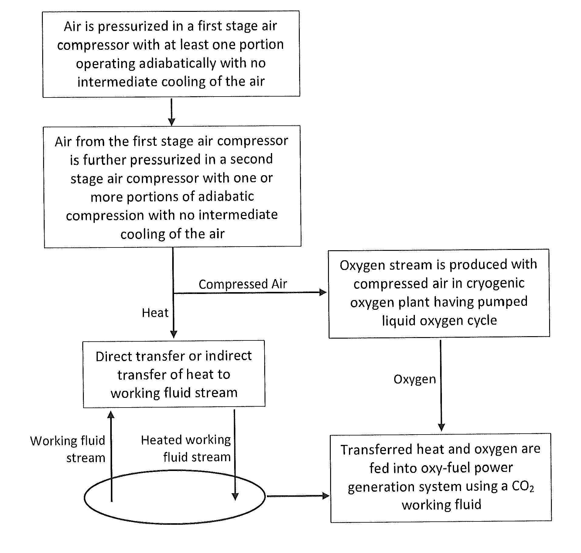
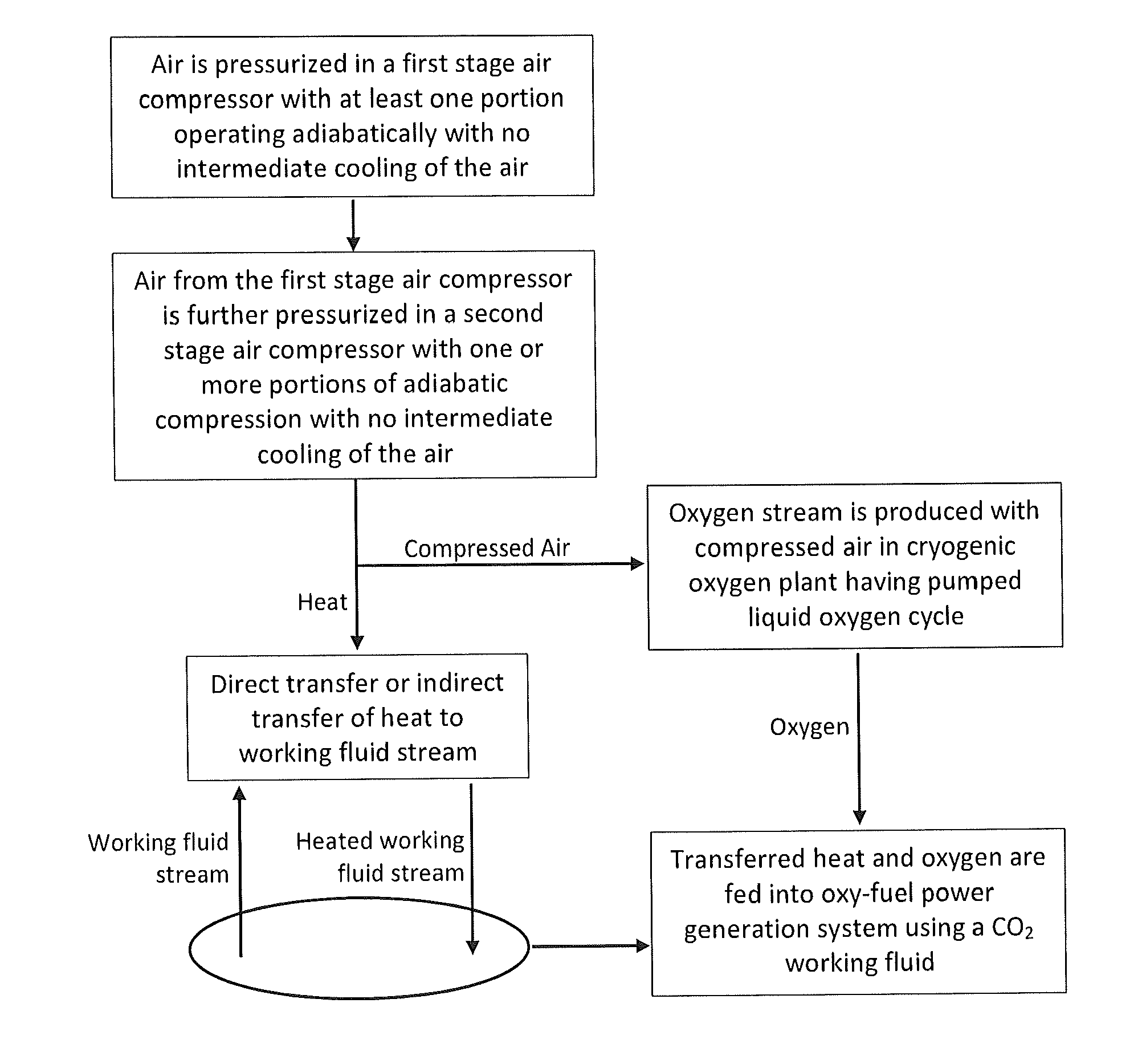
[0074]The present invention relates to air separation processes and associated systems that are particularly adapted for providing a purified product stream, particularly a purified O2 stream, and further particularly a high pressure O2 stream, from atmospheric air. The inventive methods and systems further are ad...


PUM

PropertyMeasurementUnit
pressureaaaaaaaaaa
pressure ratioaaaaaaaaaa
pressureaaaaaaaaaa

Abstract

The present invention relates to a cryogenic air separation process that provides high pressure oxygen for an oxy-fired combustion of a fuel (e.g., a carbonaceous fuel). The air separation process can be directly integrated into a closed cycle power production process utilizing a working fluid, such as CO2. Beneficially, the air separation process can eliminate the need for inter-cooling between air compression stages and rather provide for recycling the adiabatic heat of compression into a process step in a further methods wherein an additional heat supply is beneficial.

Description

CROSS-REFERENCE TO RELATED APPLICATIONS[0001]The present application claims priority to U.S. Provisional Patent Application No. 61 / 453,381, filed Mar. 16, 2011, the disclosure of which is incorporated herein by reference in its entirety.FIELD OF THE INVENTION[0002]The present invention is directed to methods and systems for separating air to provide a purified stream of one or more individual components thereof. Particularly, the methods and systems can be used to provide a purified O2 stream while simultaneously withdrawing heat of compression for use in a different or related method or system.BACKGROUND OF THE INVENTION[0003]Atmospheric air is recognized to comprise a number of different gaseous components, primarily nitrogen and oxygen, but also minor amounts of other materials, such as noble gases, methane, water vapor, and carbon dioxide. One or more of the components of atmospheric air can be separated and provided in a purified form through use of an air separation method and...

Claims


Application Information

Patent Timeline
Patent Type & Authority Patents(United States)
IPC IPC(8): F25J1/00F25J3/04F01K25/10F23L7/00C01B32/50
CPCF25J3/0409F01K25/103F23L7/007F25J3/04018F25J3/04533F25J3/04618F25J2230/04F25J2230/06F25J2240/70F25J2240/80F25J2260/80F25J2290/12Y02E20/344Y02E20/34F01K25/10F25J3/04
Inventor ALLAM, RODNEY JOHNFETVEDT, JEREMY ERON
Owner 8 RIVERS CAPTTAL LLC
Why Eureka
Try Eureka