

Acoustic transducer and microphone
a transducer and microphone technology, applied in the direction of electrical transducers, deaf-aid sets, miconductor devices, etc., can solve the problems of harmonic distortion in the output signal, inability to achieve the maximum input sound pressure of the microphone, and inability to achieve the maximum output sound pressure, etc., to prevent the leakage of signals and noise transmission, the parasitic capacitance generated between the leak pressure regulation portion and the fixed electrode plate can be reduced, and the effect of preventing the leakag
- Summary
- Abstract
- Description
- Claims
- Application Information
AI Technical Summary
Benefits of technology
Problems solved by technology
Method used
Image

Examples
embodiment 1
[0070
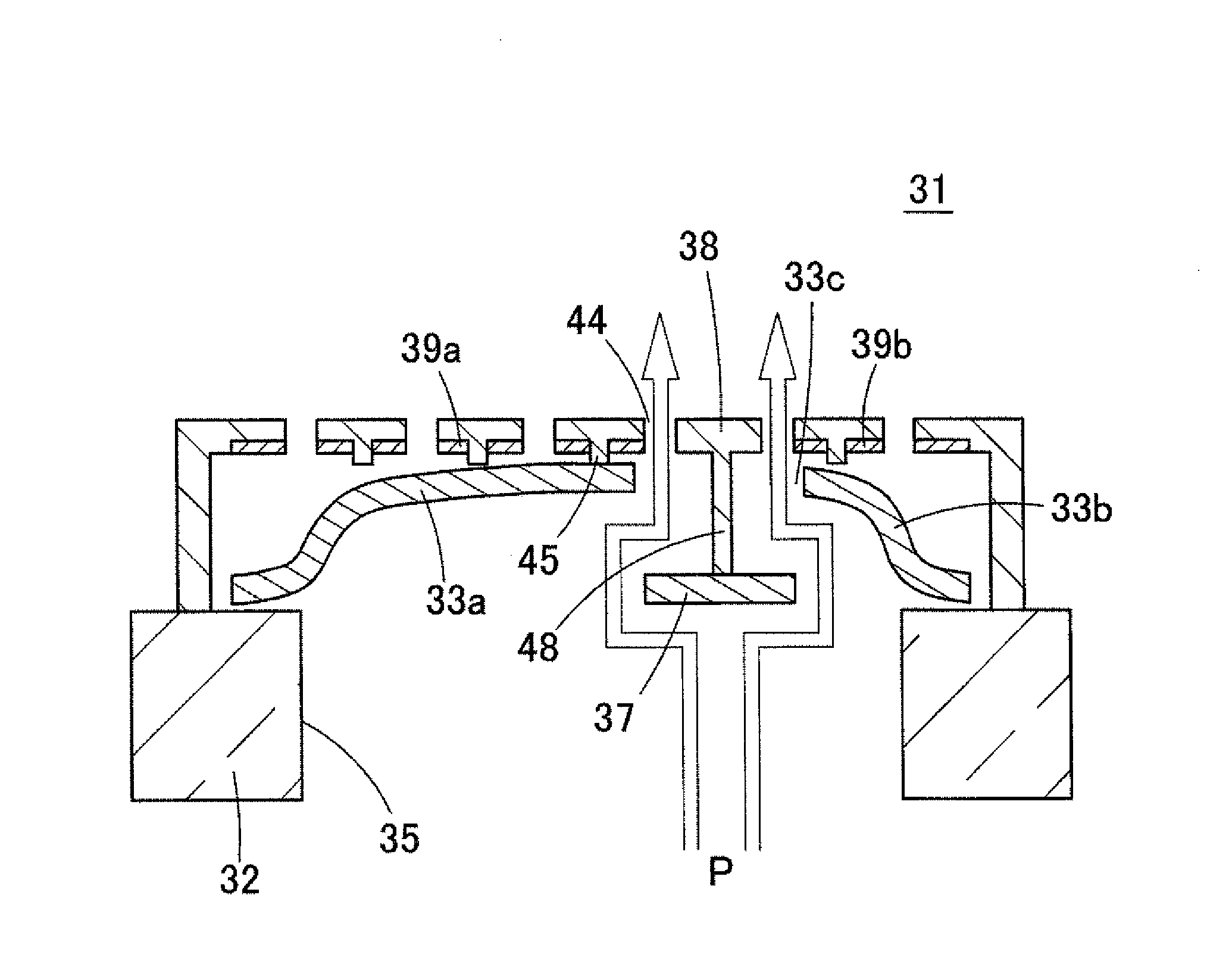
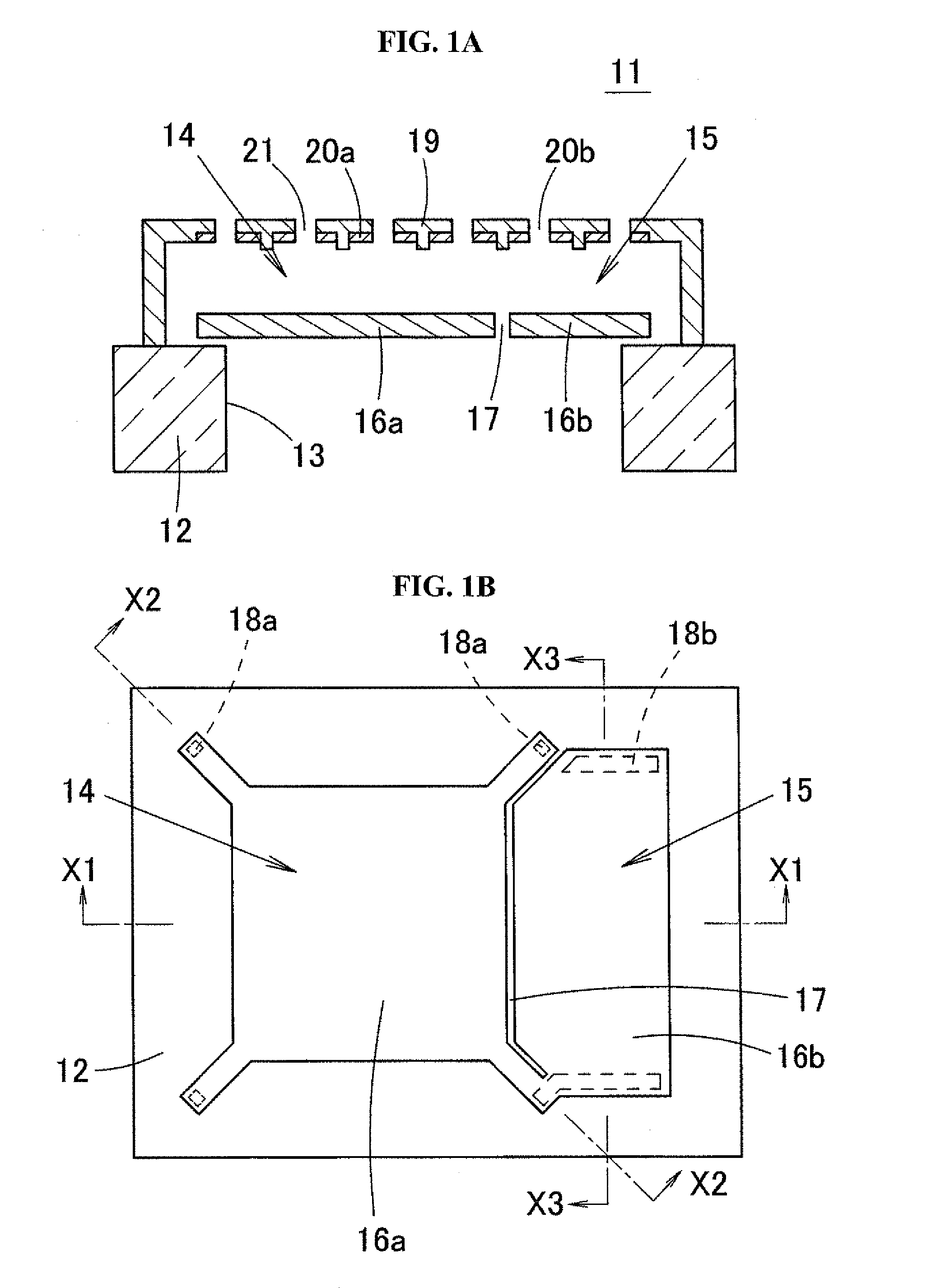
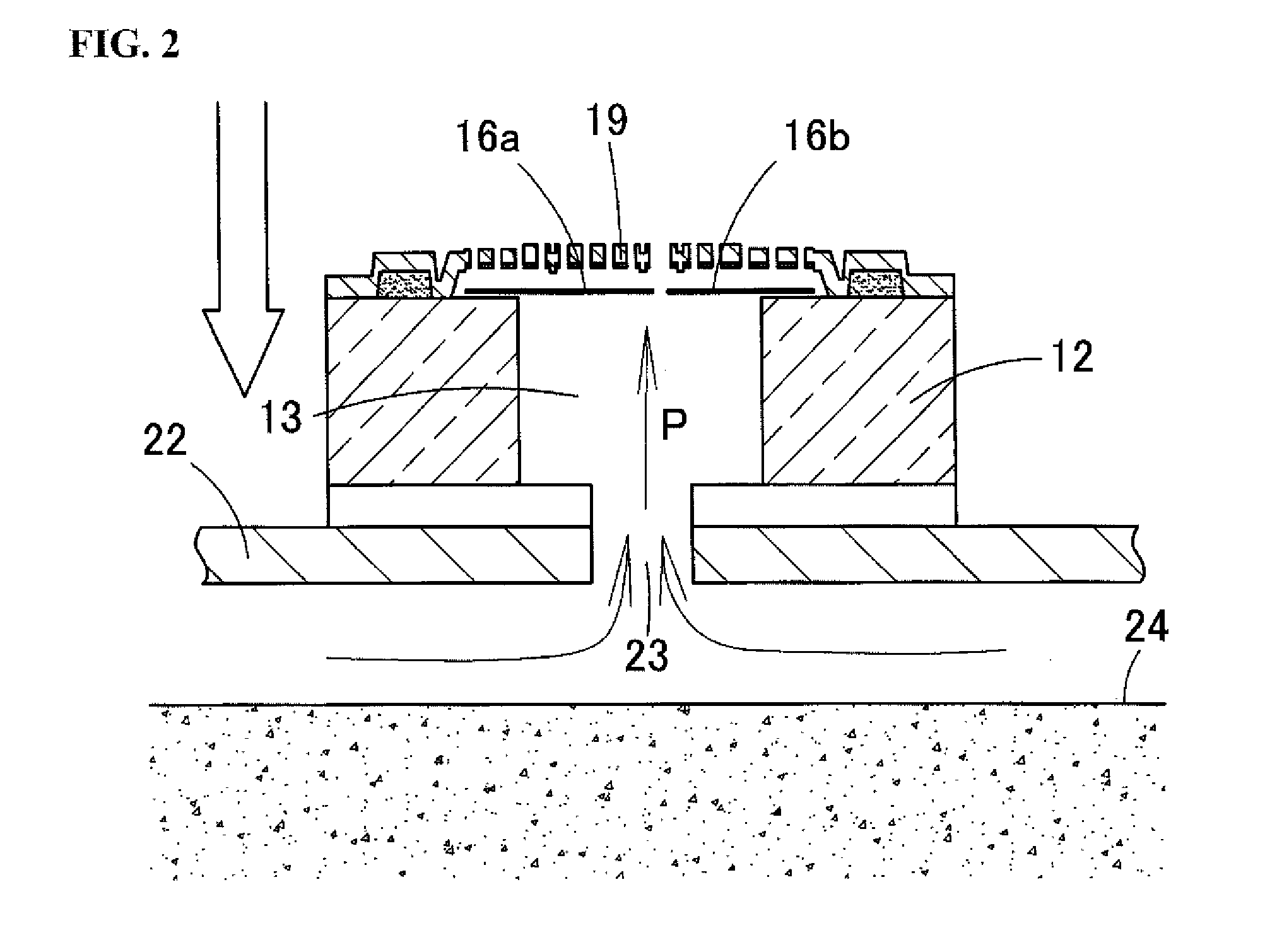
[0071]The following describes the structure of an acoustic sensor according to Embodiment 1 of the present invention with reference to FIGS. 4 to 7. FIG. 4 is an exploded perspective view of an acoustic transducer according to Embodiment 1 of the present invention, that is to say an acoustic sensor 31. FIG. 5 is a cross-sectional diagram of the acoustic sensor 31. FIG. 6 is a plan view of the acoustic sensor 31. FIG. 7 is a plan view of the acoustic sensor 31 from which a back plate 38, a protective film 50, and the like have been removed, and shows a state in which a diaphragm 33 (vibrating electrode plate) and a fixed electrode plate 39 are overlapped with each other above a substrate 32.
[0072]The acoustic sensor 31 is a capacitance type of device created using MEMS technology. As shown in FIGS. 4 and 5, in the acoustic sensor 31, the diaphragm 33 is provided on the upper surface of a substrate 32, which is made of a silicon substrate or the like, via anchors 36a and 36b, a c...
embodiment 2
[0117
[0118]FIG. 19A is a plan view showing an acoustic sensor 61 according to Embodiment 2 of the present invention, in a state in which a back plate 38 has been removed. FIG. 19B is a schematic cross-sectional diagram showing a state in which high-load pressure P has been applied to the acoustic sensor 61. In the acoustic sensor 61 of Embodiment 2, recessions 62 that are recessed toward the interior of the diaphragm 33 in the shape of a notch (void portions for allowing pressure to escape) are formed in the sides (outer peripheral portions) of the diaphragm 33 as shown in FIG. 19A. Specifically, the recessions 62 are provided in regions between adjacent leg pieces 46 on the sides of the first diaphragm 33a that are not adjacent to the second diaphragm 33b. Alternatively, the recessions 62 may be provided on the long side of the second diaphragm 33b that is not adjacent to the first diaphragm 33a, or the recessions 62 may be provided on the sides of both the first diaphragm 33a and ...
embodiment 3
[0121
[0122]FIG. 20A is a schematic cross-sectional diagram of an acoustic sensor 71 according to Embodiment 3 of the present invention. FIG. 20B is a plan view of the acoustic sensor 71 in a state in which the back plate 38 has been removed. In the acoustic sensor 71 of Embodiment 3, a barrier electrode 72 is provided in a region of the lower surface of the back plate 38 that opposes the regulation portion 37. The barrier electrode 72 is formed by a conductive polysilicon thin film, and is created using the same material and the same process as the first fixed electrode plate 39a and the second fixed electrode plate 39b in the manufacturing process for the acoustic sensor 71. The barrier electrode 72 extends along the boundary between the first diaphragm 33a and the second diaphragm 33b, that is to say substantially from end to end along the length direction of the regulation portion 37. Note that the barrier electrode 72 may be grounded, or may be kept at a certain potential.
[0123]...
PUM
 Abstract
Description
Claims
Application Information