
STED microscopy with pulsed excitation, continuous stimulation, and gated registration of spontaneously emitted fluorescence light

a fluorescence light and microscopy technology, applied in the field of sted fluorescence light microscopic method and sted fluorescence light microscope, can solve the problems of small signal yield in fluorescence light microscopic methods using multi-photon excitation, and high cost of pulsed lasers. , to achieve the effect of reducing the cost of pulsed lasers, and reducing the cost of pulsed

Active Publication Date: 2017-01-24
DEUTES KREBSFORSCHUNGSZENT STIFTUNG DES OFFENTLICHEN RECHTS +1
View PDF12 Cites 7 Cited by
  • Summary
  • Abstract
  • Description
  • Claims
  • Application Information

AI Technical Summary

Benefits of technology

The present invention relates to a method and apparatus for observing fluorescent entities in a sample using a STED fluorescence light microscopic technique. This method involves applying pulses of excitation light to the sample to excite the fluorescent entities for fluorescence, and then using a continuous wave of de-excitation light to de-excite the same entities. The fluorescence light spontaneously emitted by the excited entities after each pulse of excitation light is then registered, and the process is repeated at different positions in the sample to observe any fluctuations caused by movements of the fluorescent probes in the sample. The invention provides a way to observe and analyze the behavior of fluorescent entities in a sample with high precision and resolution.

Problems solved by technology

Pulsed lasers delivering high intensity pulses are expensive, particularly, if the pulses have to be very short, i.e. shorter than the lifetime of the excited state of the fluorescent entities, during which the excited state already decays by spontaneous emission of fluorescence light, as otherwise there would be no excited fluorescent entities left after each pulse of the de-excitation light, even in the zero point of its intensity distribution.
The signal yield in any fluorescence light microscopic method using multi-photon excitation, however, is only small, and suitable pulsed light sources for exciting fluorescent entities in a multi-photon process, which have a suitable output intensity, are expensive.
Thus, a need remains for STED fluorescence light microscopy using a low-cost continuous wave laser but nevertheless exhibiting an uncompromised spatial resolution.

Method used


Image

  • STED microscopy with pulsed excitation, continuous stimulation, and gated registration of spontaneously emitted fluorescence light
  • STED microscopy with pulsed excitation, continuous stimulation, and gated registration of spontaneously emitted fluorescence light
  • STED microscopy with pulsed excitation, continuous stimulation, and gated registration of spontaneously emitted fluorescence light

Examples


Embodiment Construction

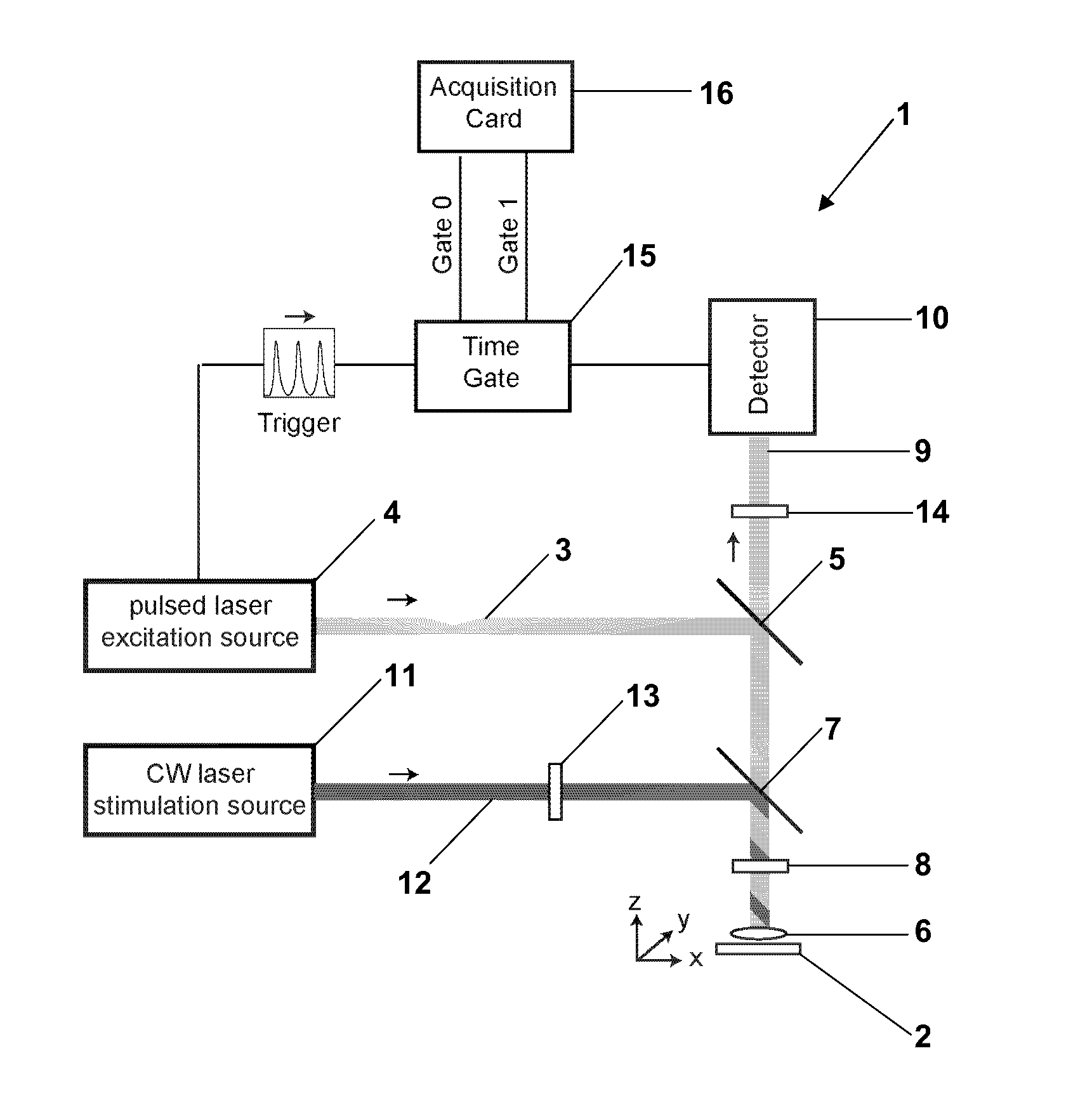
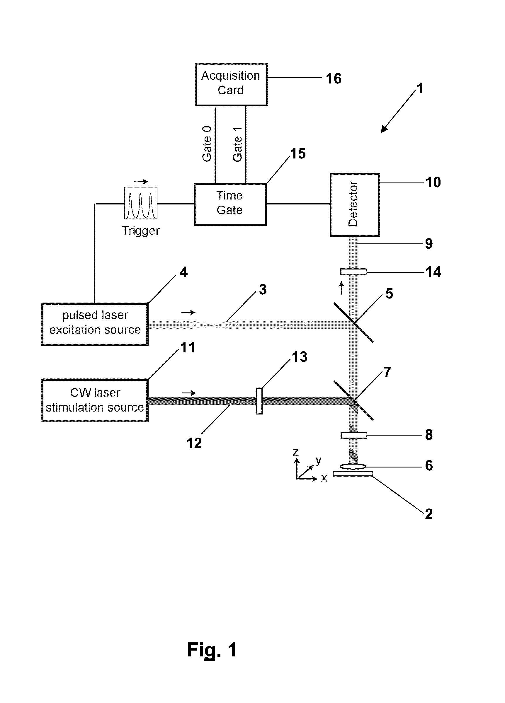
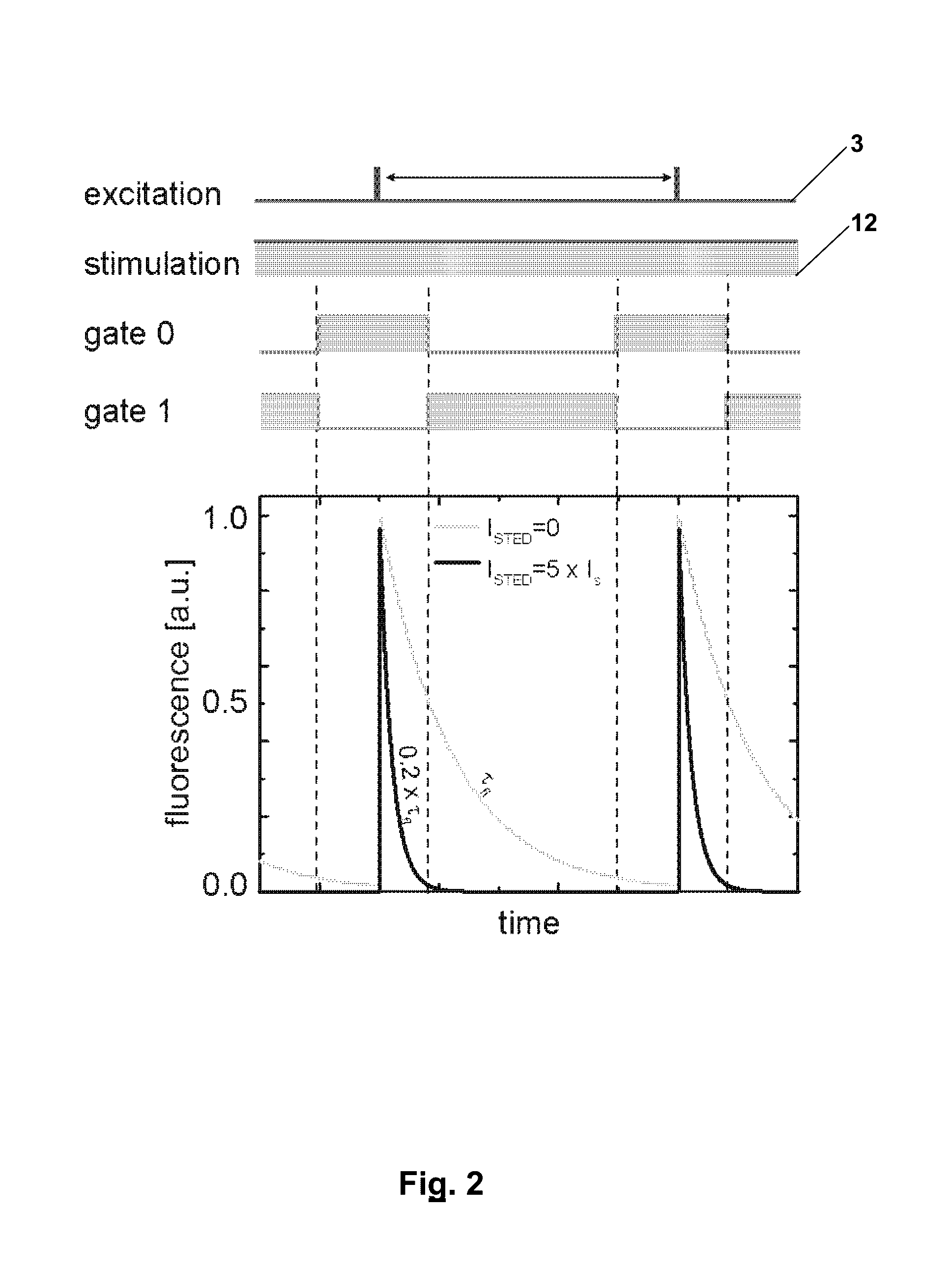
[0021]Both in the new STED fluorescence light microscopic method of imaging a structure which is marked with fluorescent entities in a sample, and in the new STED-FCS method of observing fluctuations of fluorescent entities contained in a sample within a spatially limited volume of the sample, the fluorescence light emitted by the excited fluorescent entities is registered with high temporal resolution between consecutive pulses of the excitation light. I.e., even with a typical repetition rate of the pulses of the excitation light in the order of some ten MHz, the temporal resolution has to be considerably higher than the reciprocal value of this repetition rate. According to the present invention, the registration of the spontaneously emitted fluorescence light does not take place sometime between the pulses of the excitation light but during a defined interval in time in each period started with each pulse of the excitation light. This allows for discarding or not registering par...


PUM

PropertyMeasurementUnit
time gitteraaaaaaaaaa
light poweraaaaaaaaaa

Abstract

In a STED fluorescence light microscope pulses of excitation light (3) are applied to a sample, which excite fluorescent entities contained in the sample for fluorescence, and which are focused on at least one focal area. Further, de-excitation light (12) is applied to the sample, which de-excites the excited fluorescent entities and which comprises an intensity zero point in the at least one focal area, as a continuous wave. Fluorescence light emitted by the excited fluorescent entities in the sample is registered after each pulse of the excitation light (3) and overlapping with applying the de-excitation light (13) with high temporal resolution between consecutive pulses of the excitation light (3).

Description

CROSS-REFERENCE TO RELATED APPLICATION[0001]This application is a continuation-in-part of copending PCT Application No. PCT / EP2010 / 067956, filed Nov. 22, 2010, entitled, “STED Microscopy with Pulsed Excitation, Continuous Stimulation, and Gated Registration of Spontaneously Emitted Fluorescence Light.”FIELD OF THE INVENTION[0002]The present invention generally relates to a STED fluorescence light microscopic method and to a STED fluorescence light microscope suitable for executing this method. Particularly, the STED fluorescence light microscopic method may be executed for imaging a structure which is marked with fluorescent entities in a sample, or as a fluorescence correlation spectroscopic (FCS) method of observing fluctuations of fluorescent entities contained in a sample within a spatially limited volume of the sample.[0003]The fluorescent molecules may particularly be fluorescent molecules or fluorescent quantum dots.BACKGROUND OF THE INVENTION[0004]Stimulated emission depleti...

Claims


Application Information

Patent Timeline
Patent Type & Authority Patents(United States)
IPC IPC(8): F21V9/16G01N21/64G01N21/63G02B21/00G02B21/16
CPCG01N21/64G01N21/636G01N21/6408G01N21/6458G02B21/0076G02B21/16
Inventor HELL, STEFAN W.ENGELHARDT, JOHANNREUSS, MATTHIASWESTPHAL, VOLKEREGGELING, CHRISTIANMONERON, GAELHAN, KYU-YOUNGVICIDOMINI, GIUSEPPEWILLIG, KATRIN
Owner DEUTES KREBSFORSCHUNGSZENT STIFTUNG DES OFFENTLICHEN RECHTS
Learn More