Contrast agent injection system for sonographic imaging

a sonographic imaging and contrast agent technology, applied in the field of sonographic imaging methods and devices, can solve the problems of limited clinical use of contrast agents, no contrast agent indicated for contrast enhancement during ultrasound, and limited use in cardiac and vascular applications

Active Publication Date: 2017-01-31
FEMASYS INC
View PDF378 Cites 15 Cited by
  • Summary
  • Abstract
  • Description
  • Claims
  • Application Information

AI Technical Summary

Benefits of technology

[0033]An advantage of the present invention is that contrast medium flow is controlled so that some or all of the contrast medium composition may be provided to a body structure. The flow of the contrast medium out of the device and / or out of a catheter, and to a body structure may be controlled so that providing the contrast medium may be in a continuous flow or intermittent flow, such as providing some contrast medium, stopping the flow, providing contrast medium, stopping the flow, and so on. The container(s) of a contrast medium device may be refilled one or more times during a procedure. The flow of contrast medium to the structure may be controlled automatically or by an operator. The rate of delivery of contrast medium may be controlled. The rate of delivery may be in a range from fast to slow, and is primarily controlled by the rate of force applied to the component(s) for providing force upon the fluid contained within the container(s). In an embodiment wherein the contrast medium device comprises two containers, such as two syringe bodies, and the component for providing force upon the fluid contained within each container is a plunger, the rate of force applied to the fluid in each container is identical when the plungers are activated simultaneously with the same force applied, to provide the same rate of delivery of contrast medium from the device.
[0034]An embodiment of the present invention comprises visualization of at least one fallopian tube using a catheter placed at or near the opening of the fallopian tube. Any device that provides a catheter to the fallopian tube, may be used. A catheter may be connected to the contrast medium device comprising a container assembly described herein. A particular device for providing a catheter to a body structure, such as a fallopian tube, and that may be useful in methods of visualizing a fallopian tube is the device taught in U.S. patent application Ser. No. 11 / 065,886, U.S. patent application Ser. No. 12 / 240,738, and U.S. patent application Ser. No. 12 / 240,791, now U.S. Pat. Nos. 8,048,086, 8,048,101, and 8,052,669, each of which is herein incorporated in its entirety. In general these applications disclose a device comprising a housing and an introducer shaft that is used to enter and traverse the uterus until the tip of the shaft approaches or touches the fundus of a uterus. Once the tip of the introducer shaft is at the fundus of the uterus, the device may be stabilized. One or more catheters, such as two, are fed through the introducer shaft and out into the uterine cavity. The placement of the introducer shaft allows for the three dimensional alignment of the catheter(s) with the cornua of the uterus. The catheter(s) is advanced until the delivery end(s) of the catheter(s) are in place in the cornua. An end structure, such as a balloon, is inflated or engaged, to stabilize the catheter(s) in place, and the end structure may prevent or minimize back-flow of materials exiting the catheter delivery end. Once the end structure is engaged, the catheter(s) is ready for delivery of materials or other activities.
[0035]In a method of the present invention, the catheter placed by the introducer shaft comprises a catheter assembly. The end of the catheter opposite the delivery end, referred to herein as the proximal end or the attachment end, is attached to a contrast medium device of the present invention. The contrast medium is generated by the actions of the container assembly and the contrast medium is provided into and through the catheter(s) and out into the cornua of the uterus and into a fallopian tube(s). Visualization techniques are initiated as the contrast medium enters the fallopian tube(s) and if possible, flows through the tube(s) and out into the peritoneal cavity. If a tube is blocked, the medium will not flow in that tube but may flow to a second, the contralateral, tube if that second tube is not blocked. The pressure built up by the blockage may or may not unseat an end structure on the catheter, such as a balloon, in an effort to relieve pressure, but if the end structure of the catheter is moved, the flow would then be directed into the uterus or the unblocked tube.
[0036]If the device providing the catheter uses only one catheter, then visualization of one fallopian tube occurs, followed by readjustment of the device, such as rotation of the introducer shaft, as taught in the cited patent applications, and the steps are repeated to provide a contrast medium to the other fallopian tube. The contrast medium provided may be any currently known contrast medium that may be provided through a catheter to a location.
[0037]An embodiment of the present invention comprises using a contrast medium device and catheter to provide contrast medium to the uterus for visualizing at least one fallopian tube, or visualization of at least a portion of the uterus and at least one fallopian tube. When the structure to be visualized is a at least one fallopian tube, or a uterus and / or at least one fallopian tube, a contrast media device of the present invention, in combination with a catheter may be used. A catheter having elements for preventing retrograde flow of fluid from the uterus may be connected to a contrast medium device comprising a container assembly as described herein. Catheters with element(s) that prevent retrograde flow are known in the art, and it is within the skill of those in the art for selecting a catheter to attach to a contrast media device of the present invention to use in methods taught herein.
[0038]In a method of the present invention, a catheter, such as a balloon catheter, is a catheter assembly. In the method, the delivery end of a catheter is placed in the uterus, and optionally, the structure to prevent retrograde flow into the cervix is employed, for example, the balloon of a balloon catheter is expanded. The end of the catheter opposite the delivery end, referred to herein as the proximal end or the attachment end, is attached to a contrast medium device of the present invention. The contrast medium is generated by the actions of the device and the contrast medium is provided into and through the catheter(s) and out into the uterus. The desired amount of contrast medium is provided and visualization techniques are initiated, and can be used to visualize the movement of the contrast medium into the uterus, to visualize at least a portion of the structure of the uterus, for example, by providing the contrast medium, and / or to visualize entry, transit and / or exit of the contrast medium in at least one fallopian tube. If a fallopian tube is blocked, the contrast medium will not flow past the blockage but may flow to the contralateral tube if not blocked. The pressure built up by the blockage may or may not be detected by an element of the contrast medium device that is designed to detect the fluid back pressure created by the lack of continued flow of the fluid through the structure and / or conduits. Should the desired pressure be reached, the contrast medium flow may be halted, such as by a medical professional providing contrast medium may stop applying pressure to the contrast medium device, and cease providing fluid through the catheter to the uterus. The contrast medium provided may be any currently known contrast medium that may be provided through a catheter to a location, or may be the liquid / air contrast medium disclosed herein.

Problems solved by technology

Tubal patency and tubal occlusion can be assessed only under ideal sonographic conditions, limiting its usefulness clinically.
Currently, no contrast agent indicated for contrast enhancement during ultrasound evaluation of the uterine cavity and fallopian tubes is available in the U.S. Other ultrasound contrast agents are available for widespread use but are limited to use in cardiac and vascular applications.
Stability and persistence become major issues for such small microbubbles and air bubbles in this size range persist in solution for only a short time.
Therefore, availability of contrast agents, procedural challenges, particularly during preparation of the patient and the contrast materials, and cost are disadvantages associated with known contrast media used sonographically.
Although conventional contrast agents function adequately, the disadvantages inherent in the conventional agents create a need for better contrast agents.
One disadvantage with currently used contrast agents is that they are very expensive and difficult for some physicians to obtain.
Another disadvantage is that conventional contrast agents must be shaken prior to injection to either mix the components or to generate bubbles, thus making the entire diagnostic procedure cumbersome and possibly somewhat subjective.
A third disadvantage is that the contrast agent composition has a very short shelf life due to its unstable nature once it is prepared for use in a patient.
It is known that such microbubbles are only stable for a short amount of time.
Thus, limitations to this method are that the microbubbles introduced into a fluid may coalesce into a few large bubbles or one large air pocket, the microbubbles formed must be stable long enough for visualization to occur, and due to the instability of the microbubbles, it is difficult to create reproducible conditions for comparative visualizations.

Method used


Image

  • Contrast agent injection system for sonographic imaging
  • Contrast agent injection system for sonographic imaging
  • Contrast agent injection system for sonographic imaging

Examples


example 1

Preparation of Contrast Medium with Dual Syringe Pump

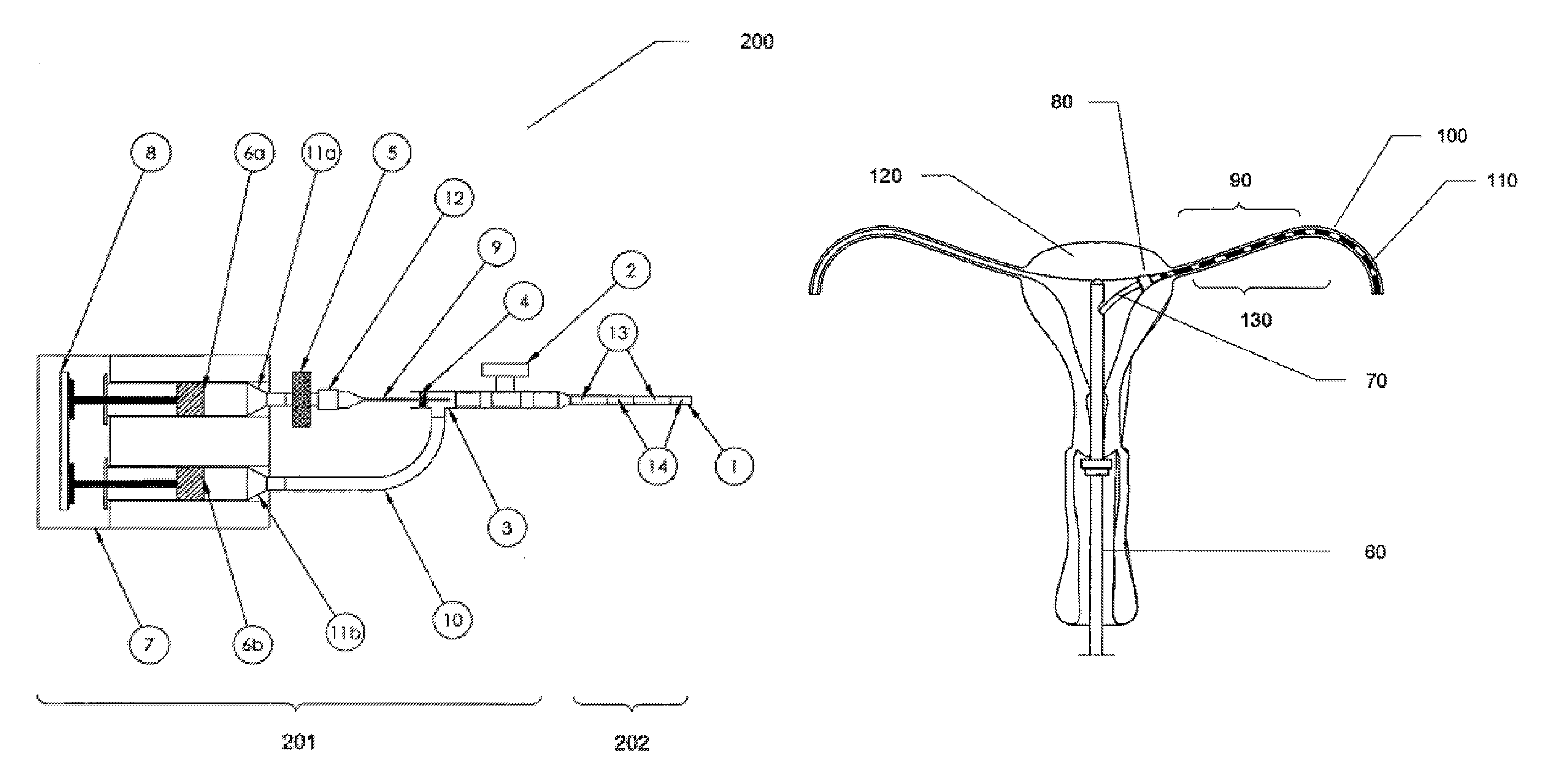
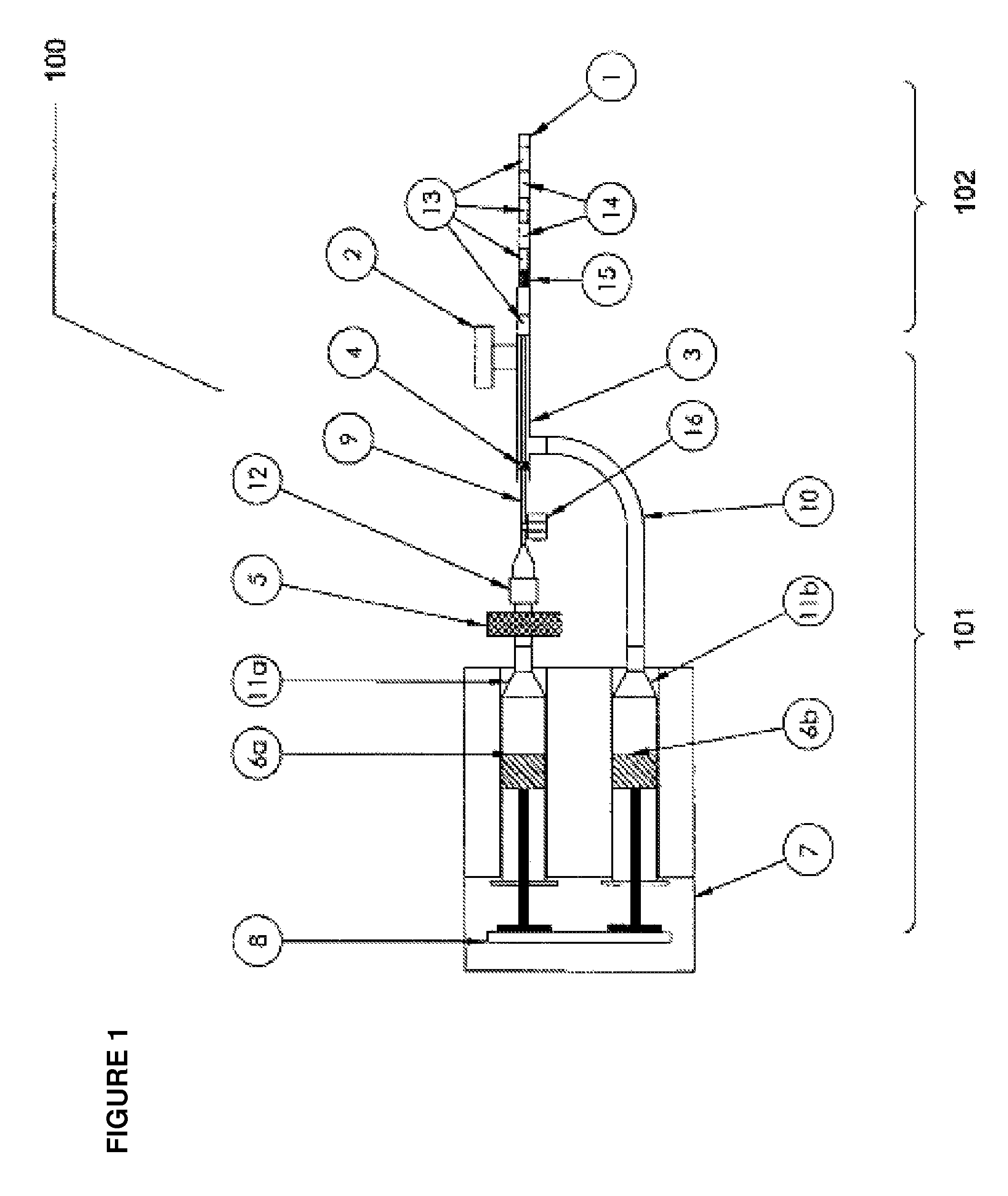
[0104]A container assembly comprising a dual pump was made, as generally depicted in FIG. 1, with two syringes, one 6 cc and the other 20 cc in volume. The 6 cc syringe was completely filled with saline and the 20 cc was filled with air. Sterile 0.2 μm filters (Sartorius Minisart or Whatman Syrfil-MF) were attached to the syringes, as sterile technique was desired. A 27 gauge, 3.5″ length spinal needle was used to inject a gas phase into a fluid phase in the contrast pattern generating chamber to create the alternating air and liquid phase interfaces. A PICC-Nate catheter T-port extension and two lengths of extension tubing were utilized in the set-up.

[0105]Variations of syringe ID, pump volume, pump rate and pump delay settings were evaluated and yielded an acceptable contrast medium, as visualized in a catheter assembly forward of the container assembly. The contrast medium was delivered into clear PVC tubing that simulated the ...

example 2

Preparation of Contrast Medium with Handheld Dual Syringes

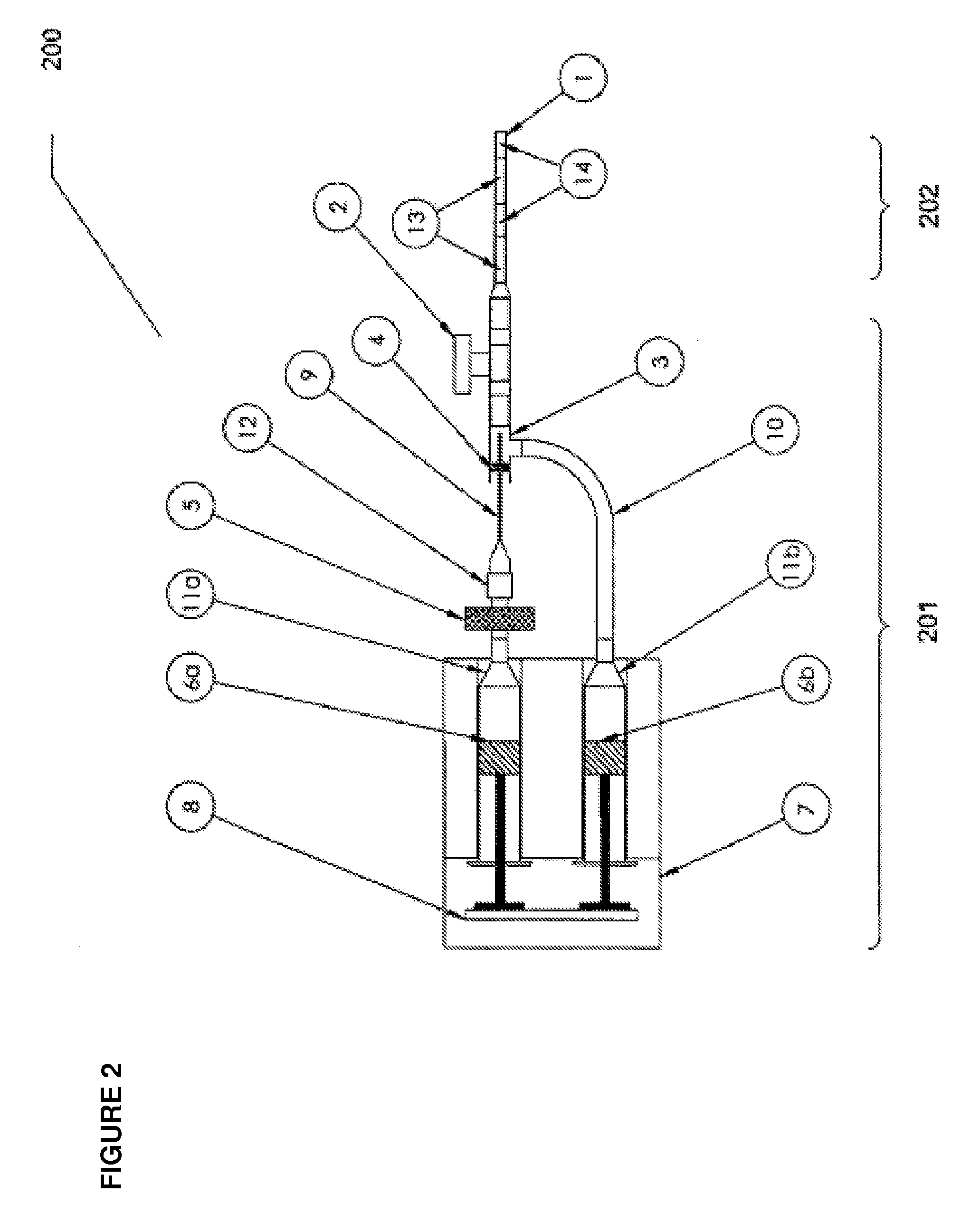
[0106]The assembly of Example 1 was followed using a housing to support the dual syringes. A block was placed behind the plunger of the 6 cc syringe containing saline to align with the plunger distance of the 20 cc syringe containing air. The creation of the contrast medium and its delivery to a catheter were controlled and manipulated by hand force on the plungers of the dual syringes as necessary to deliver the contrast medium into the catheter. When the two plungers of the syringes were pushed simultaneously, the pattern of the contrast medium was uniform, with substantially equal amounts of air and saline phases, alternating in the catheter. When one plunger was pushed, followed by pushing of the plunger of the other syringe, the pattern was sometimes regular and sometimes irregular, depending on the activation of the individual plungers. Although the sizes of the individual segments of air and saline phases were not unif...

example 3

Preparation of Contrast Medium with Syringe Containing Porous Substance

[0107]A sterile Optipore scrubbing sponge was cut lengthwise in two equal parts. The plunger from a 60 cc syringe was removed and the sponge halves were inserted, one behind the other. The plunger was reinserted in the syringe and depressed to the 15 cc mark. The syringe tip was submerged into a sterile container of saline and the plunger was withdrawn to the 30 cc mark. The container assembly was now assembled and loaded. The container assembly was attached to a catheter assembly and the plunger was depressed to create an air and saline composition, a contrast medium composition, for sonographic visualization. The contrast medium was delivered into clear PVC tubing that simulated the dimensions of the fallopian tube. An irregular pattern or random pattern was visualized as the user controlled the delivery of the contrast medium. Although the sizes of the individual segments of air and saline phases were not unif...


PUM


Abstract

The present invention comprises methods and devices for generating and providing contrast medium for sonography of structures such as ducts and cavities. The invention provides for creation of a contrast medium comprising detectable acoustic variations between two phases, for example, a gas and a liquid. Sonography is the primary imaging technique but other conventional detection techniques may also be employed with the present invention.

Description

RELATED APPLICATIONS[0001]This application claims the priority U.S. patent application Ser. No. 12 / 245,265, filed Oct. 3, 2008, PCT Application No. PCT / US2009 / 059370, filed Oct. 2, 2009, and U.S. Provisional Patent Application Ser. No. 61 / 411,856, filed Nov. 9, 2011, each of which is incorporated herein in its entirety.TECHNICAL FIELD[0002]The present invention relates to methods and devices for sonographic imaging of cavities and conduits, such as organs, ducts and other cavities. In particular, methods and devices of the present invention use detectable acoustic variations of alternating patterns of a gas phase and a liquid phase traversing a passage.BACKGROUND OF THE INVENTION[0003]Non-surgical diagnostic procedures for examining body ducts and cavities, in particular the uterus and fallopian tubes, are well known. One procedure, known as hysterosalpingography, employs contrast agents and diagnostic fluoroscopic imaging techniques for viewing the uterus and fallopian tubes. A saf...

Claims


Application Information

Patent Timeline
Patent Type & Authority Patents(United States)
IPC IPC(8): A61B8/14A61B17/42A61M5/14A61M5/145A61M5/00A61B8/08A61M31/00
CPCA61B17/42A61M5/007A61M5/1407A61M5/1452A61B8/481A61M31/005A61B8/12
Inventor LEE-SEPSICK, KATHYAZEVEDO, MAX S.
Owner FEMASYS INC
Why Eureka
Try Eureka