
Suspension and body attachment system and differential pressure suit for body weight support devices

Active Publication Date: 2017-01-31
LITE RUN
View PDF67 Cites 17 Cited by
  • Summary
  • Abstract
  • Description
  • Claims
  • Application Information

AI Technical Summary

Benefits of technology

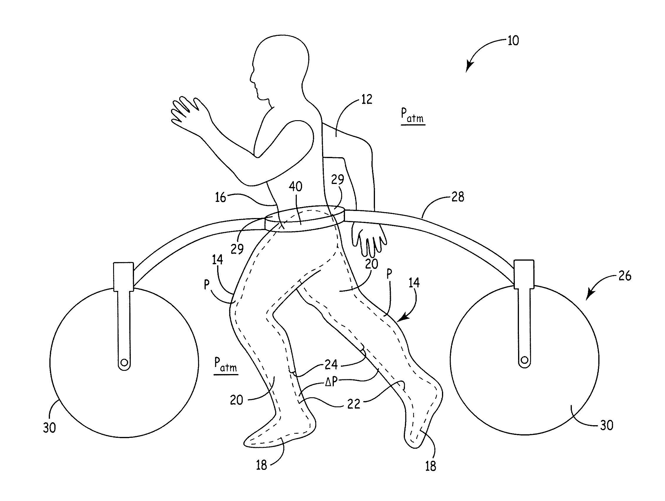
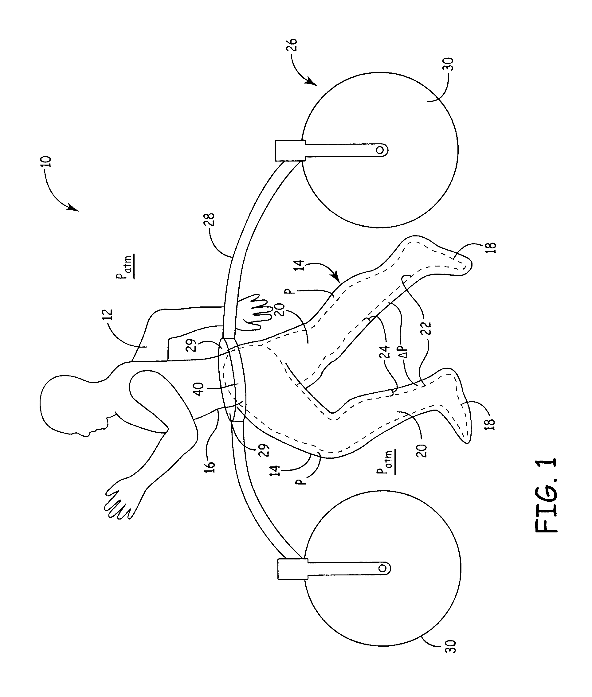
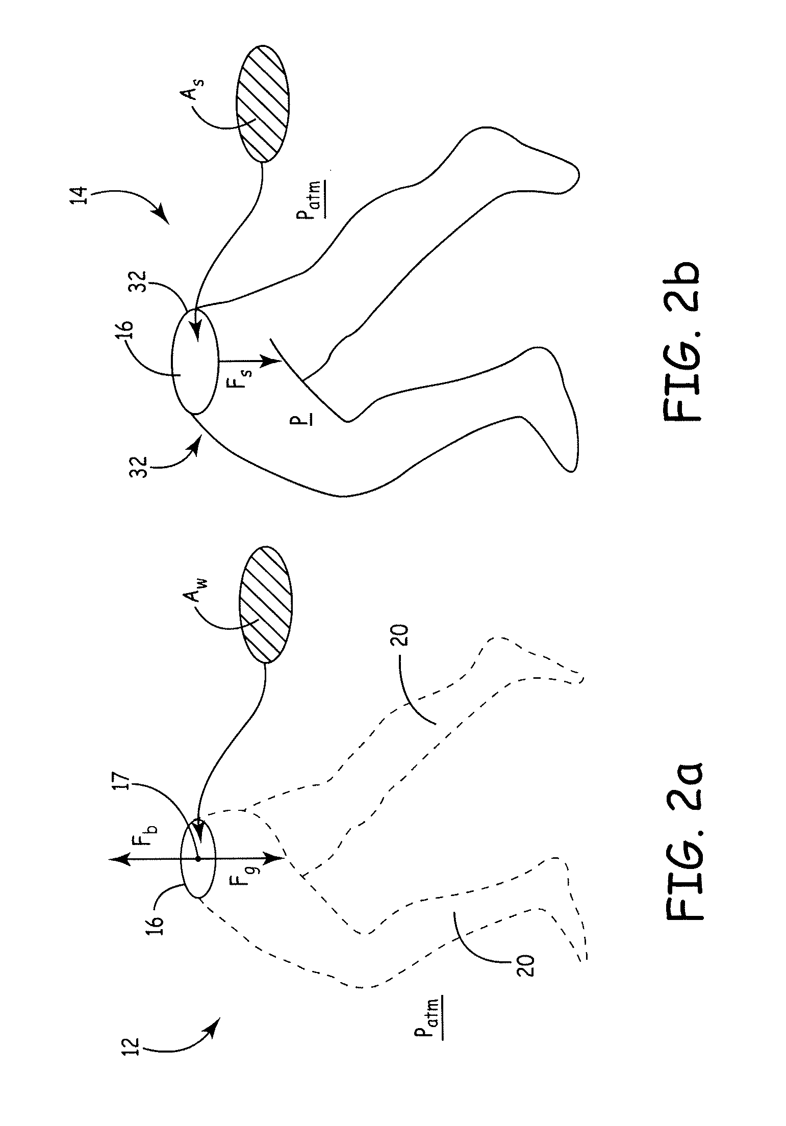
The present invention is a differential pressure body suit that provides weight support without restricting natural body movements. This suit can be used for rehabilitating joint injuries, training for athletic performance or fat reduction, or assisting the mobility of physically disabled people. The pressure / depressurization cycle helps reduce stress on joints and can also provide medical benefits such as massage or improving blood flow. This invention is useful for humans, animals and horses. The flexible and jointed body suit is designed to bend at the mammal's joints with minimal force.

Problems solved by technology

Over time, body bones or joints can become damaged.
Such damage may result from the aging process, manifested by arthritis, osteoporosis, and slips and falls.
But injuries are also caused by sports activities.
In addition to bodily injuries caused by falls, prolonged bicycling can result in groin discomfort or numbness.
These can be cumbersome and expensive systems that do not necessarily reduce the stress on the body caused by gravity.
However, these types of systems are not portable, since the person is confined to the pool or water tank.
Moreover, pools or water tanks may be unavailable or expensive to install.
But the straps and attachment devices create localized pressure points and stresses on the body, and restrict the range of motion of the body and its limbs.
Such a mechanical weight off-loading system may also lack portability.
However, this Whalen system requires a large, immobile pressure chamber containing a treadmill.
Such a system is expensive and requires cumbersome entry and exit by the person.
It will not enable the person any other means of exercise besides the treadmill.
U.S. Pat. No. 3,589,366 issued to Feather teaches exercise pants from which air is evacuated, so that the pants cling to the body of an exerciser to cause sweating, thereby leading to weight loss.
As a result, the pilot can lose situational awareness and spatial orientation.
Such pressurized body suits have not previously been used to rehabilitate skeletal joint injuries or minimize conditions that cause erectile dysfunction.
Moreover, they have typically been used only in stationary situations like a sitting pilot due to the problem of air pressure forcing the body suit off the lower torso.
However, physically impaired people often lack the strength and or balance in order to raise themselves from a sitting to a standing position without assistance.
Also providing personnel for assistance entails additional costs for rehabilitation institutions or in providing home care.
These devices generally lack having a body weight support capability.
However harness systems have the drawbacks we have described earlier.
This restricts the natural position of the body during running and walking to a forward leaning position.
Because harness systems pull the upper body directly upwards from the chest they are can provide too much stability for balance training.
Another issue with the harness based body weight support is that the harness supporting the subject decreases the need for natural associated postural adjustments (APAs) that are required for independent gait.
When supported by a harness during BWS training any mediolateral movement is restricted by a medially directed reaction force component that will help stabilize the body in the frontal plane and decrease or even eliminate the need for APAs making gait and balance training less effective.
Further the straps and attachment devices create localized pressure points and stresses on the body, and restrict the range of motion of the body and its limbs.
In particular the straps around the thighs and groin interfere with the back and forth rotation of the legs.

Method used


Image

  • Suspension and body attachment system and differential pressure suit for body weight support devices
  • Suspension and body attachment system and differential pressure suit for body weight support devices
  • Suspension and body attachment system and differential pressure suit for body weight support devices

Examples


example 1

Mobile Support Device

[0213]A rigid band is constructed from curved rigid aluminum strip 1 inch wide and ⅛ inch thick. The band is oval in shape. Pulleys we attached to the band as follows. Two pulleys are attached at the front and back mid-points of the band, two pulleys are attached at the midpoints at the side in the configuration shown in FIG. 47. On each side two more a pulley is attached frontwards on the band from the midpoint pulley and another pulley is attached rearwards. To attach the pulleys to the pants rigid supporting bars are constructed of ⅛″ thick ¾″ wide aluminum bars are inserted into sleeves sewn into the pants as shown in FIG. 46. A cord made from a low stretch material run alternatively through band pulleys and the suit pulleys and tied in a knot. The cord is adjusted so that the pants pulleys are 4 inches below the waist. One half inch diameter pegs are bolted to the band at the midpoint on each side to serve as attachment pegs to the horizontal C-shaped secti...

example 2

Powered Mobile Support Device

[0215]A mobile ‘walker’ device has been constructed using the concepts illustrated in FIG. 54. A standard commercially available rollator frame was used as a mechanical base. Compression springs (Century Spring) that yield about 50 pounds for 6 inches of compression were used, one on each side as per the FIG. 54. Gear motors that displace the springs were used. The pressure pants, bend and pulley attachment mechanism as described in Example 1 were employed identically in this design, except that the band is pushed up with the compression spring mechanism, instead of pulled up or tensioned with the over-hanging suspensions system. A 24 lead acid battery source is used to power a portable air pump (Thomas), an air regulator (Bellofram), the gear motor, load cell and pressure sensors, and an electronics PLC controller (Galil Inc).


PUM

PropertyMeasurementUnit
Fractionaaaaaaaaaa
Fractionaaaaaaaaaa
Fractionaaaaaaaaaa

Abstract

The present invention provides a differential pressure body suit with external support against body suit migration. In its preferred embodiment, such body suit may comprise a close-fitting, multi-layered suit sealed against a mammal's skin to contain the differential pressure, or a looser-fitting suit that bends at the mammal's joints with minimal force. External support means include either fixed or movable mechanical supports attached to the body suit, extraordinary air pressure levels for making the body suit rigid, or exoskeletons attached to the body suit, or a counter-force suspension cable adjustment system. A cyclic control system can turn the differential pressure condition within the body suit on and off on a selective basis to accommodate the movement of the legs of the mammal. This differential pressure body suit provides a portable and convenient system for, e.g., rehabilitating a skeletal joint injury or training the mammal for injury prevention or athletic performance or fat burning. The pressurization reduces the weight of the body to greater or lesser extents, and offloads the weight to the ground through the external support means.

Description

CROSS-REFERENCE TO RELATED APPLICATION[0001]This application claims the benefit of the U.S. provisional application No. 61 / 626,749 entitled “Suspension and Body Attachment System and Differential Pressure Suit for Body Support Devices” filed on Oct. 3, 2011, and is a continuation-in part of U.S. Ser. No. 12 / 456,196 filed on Jun. 12, 2009, which is a continuation-in-part of U.S. Ser. No. 12 / 319,463 filed on Jan. 7, 2009, which claims the benefit of U.S. provisional application No. 61 / 010,034 filed on Jan. 7, 2008, and 61 / 131,919 filed on Jun. 13, 2008, all of which are hereby incorporated by reference.FIELD OF THE INVENTION[0002]This invention relates generally to the motion and physical health of the mammalian body, and more specifically to portable systems for assisting humans or other animals to medically rehabilitate or train specific body parts through the application to such body parts of differential pressure.BACKGROUND OF THE INVENTION[0003]Vertebrate animals feature a flexib...

Claims


Application Information

Patent Timeline
IPC IPC(8): A61H3/04A61H3/00A61H9/00A41D13/002A41D13/00
CPCA61H9/0078A61H3/008A61H3/04A41D13/0007A63B2208/053A63B2208/056A61H2003/007A41D13/0025A61D3/00A61F5/24A61H3/00A61H2201/0103A61H2201/1616A61H2201/1621A61H2201/163A61H2201/1642A61H2201/1647A61H2201/165A61H2201/5071A61H2203/03A61H2205/08A61H2205/10A61H2209/00A63B21/00181A63B21/153A63B22/0056A63B22/02A63B22/0235A63B22/20A63B69/0064A63B71/0009A63B2022/0094A63B2208/05A63B2208/14A63B2220/56B32B5/04B32B5/26B32B2307/51B32B2307/724B32B2307/7242B32B2437/00B32B2535/00
Inventor JOHNSON, DOUGLAS E.HAUCK, JOHN A.OSLAND, ODDJOHNSON, MARK T.
Owner LITE RUN
Learn More