Device and method for drying separated electronic components

a technology of electronic components and devices, applied in drying machines with progressive movements, lighting and heating apparatus, furniture, etc., to achieve the effects of improving control, high production speed, and little disruption

Active Publication Date: 2017-01-31
BESI NETHERLANDS BV
View PDF22 Cites 3 Cited by
  • Summary
  • Abstract
  • Description
  • Claims
  • Application Information

AI Technical Summary

Benefits of technology

[0007]The invention provides for this purpose a device of the above described type, characterized by suction means for suctioning absorbed moisture out of the moisture-absorbing material. Because the moisture is suctioned out of the moisture-absorbing material, this material does not become saturated, and it can be used for sustained drying of separated electronic components. Separated electronic components can thus be dried effectively for a longer period of time, at higher production speeds and with relatively little chance of disruption. In addition, suctioning of the moisture out of the moisture-absorbing material also has a further advantage. Suctioning moisture out of the moisture-absorbing material, instead of for instance displacing moisture by scraping, evaporation or blowing, ensures that the conditions in the space in which the separated electronic components are located can be better controlled; this is because the moisture is removed by suctioning and is therefore no longer a factor in the vicinity of the electronic components.

Problems solved by technology

At such a pressure difference a good suctioning of the moisture is achieved without this resulting in undesirable side-effects, such as for instance excess airflow whereby the separated electronic components are displaced in undesirable manner.

Method used


Image

  • Device and method for drying separated electronic components
  • Device and method for drying separated electronic components
  • Device and method for drying separated electronic components

Examples


second embodiment

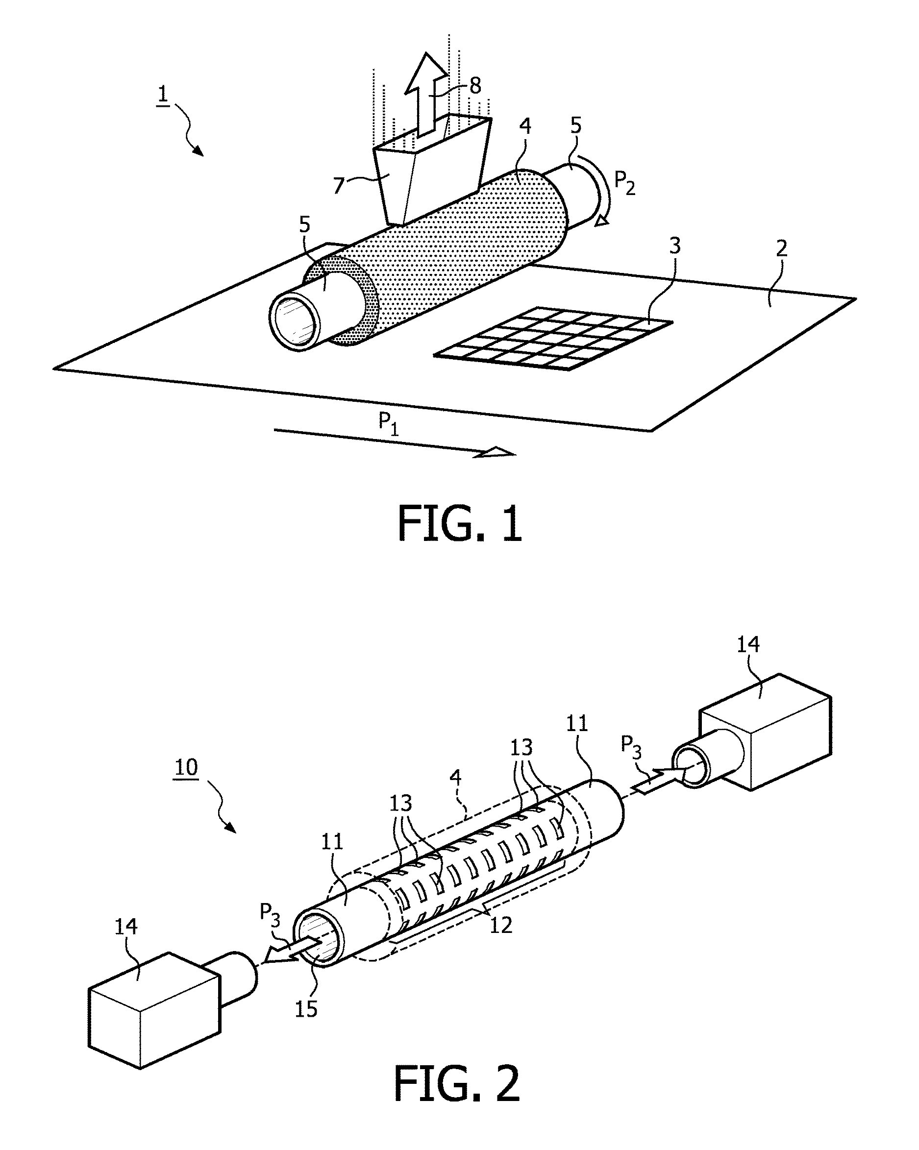
[0024]FIG. 2 shows a roller 10 which can form part of a device according to the invention. Moisture-absorbing material 4 is designated with the same reference numeral as in FIG. 1. Roller 10 consists of a tubular carrier 11, the outer side of which is partially enclosed by moisture-absorbing material 4. Tubular carrier 11 is provided with a gas and moisture-permeable segment 12. Openings 13 are arranged for this purpose in tubular carrier 11. There are diverse alternatives, such as grids and gauze, as alternative to the gas and moisture-permeable openings 13. Suction means 14 represented highly schematically connect to the hollow interior 15 of tubular carrier 11. Suction means 14 can generate an underpressure in the hollow interior 15 of tubular carrier 11 such that gas flows are created as according to arrows P3. The arrows P3 in FIG. 2 show that the suction means connect on two sides to the hollow interior 15 of tubular carrier 11, although it is of course also possible for the s...

third embodiment

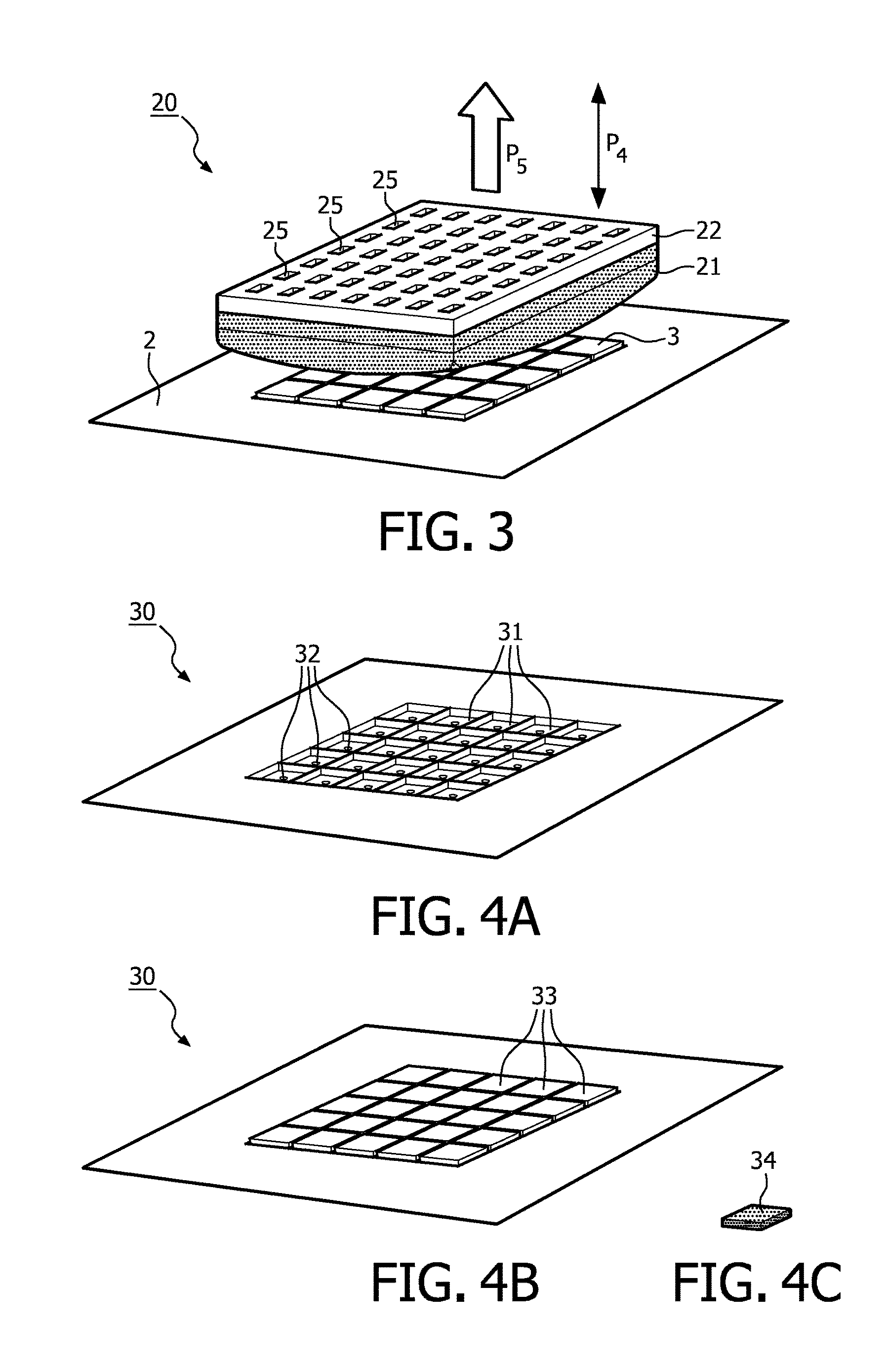
[0025]FIG. 3 shows a device 20 according to the present invention. In this embodiment moisture-absorbing material 21 is arranged on a flat holder plate 22. Holder plate 22 with moisture-absorbing material 21 can be moved intermittently (see arrow P4) relative to electronic components 24 located on a carrier 23 such that electronic components 24 are dried by means of tamponing. Arranged in holder plate 22 are openings 25 through which a gas flow can be generated (see arrow P5), whereby in this variant the gas flow is also suctioned through moisture-absorbing material 21. At least a part of the moisture present in moisture-absorbing material 21 will here be entrained in gas flow P5, as a result of which the moisture-absorbing material 21 dries and desirably does not become saturated.

[0026]FIG. 4A shows a schematic view of a carrier 30 in which a number of recesses 31 are arranged. Recesses 31 are adapted to the dimensioning of a specific size of electronic component such that these la...


PUM


Abstract

The invention relates to a device for at least partially drying separated electronic components comprising: a carrier for the electronic components; a moisture-absorbing material; and a holder covered with the moisture-absorbing material, wherein the holder and the carrier are displaceable relative to each other such that the electronic components for drying can be brought into contact with the moisture-absorbing material.

Description

BACKGROUND OF THE INVENTION[0001]1) Field of the Invention[0002]The present invention relates to a device and method for drying separated electronic components.[0003]2) Description of the Prior Art[0004]During the process of manufacturing electronic components, such as more particularly semiconductor products, these are usually separated (which can also be referred to as singulated or divided) from a larger unit of electronic components. The electronic components are usually manufactured in a larger unit of electronic components. Examples hereof are for instance packages with a plurality of encapsulated electronic components, and wafers. During separation use is generally made during machining processes of flushing liquid, although the separation can also take place using a cutting liquid. For the least possible impact on the processing steps following separation, it is desirable that the separated electronic components are dried before they are subjected to other processing steps.[...

Claims


Application Information

Patent Timeline
Patent Type & Authority Patents(United States)
IPC IPC(8): F26B3/00H01L21/67F26B5/16H01L21/683H01L21/673
CPCH01L21/67028F26B5/16H01L21/67034H01L21/67046H01L21/67092H01L21/67336H01L21/6838
Inventor HUISSTEDE, JURGEN HENDRIKUS GERHARDUSIN DEN BOSCH, WILHELMUS JOHANNES
Owner BESI NETHERLANDS BV
Why Eureka
Try Eureka