
Monitoring transport network infrastructure

a technology for transport networks and infrastructure, applied in the direction of structural/machine measurement, solids analysis using sonic/ultrasonic/infrasonic waves, instruments, etc., can solve the problems of reducing or cancelling services on the network, limiting the time available, and affecting the service life of the network, so as to achieve low installation and maintenance costs

Active Publication Date: 2017-02-07
OPTASENSE HLDG LTD
View PDF24 Cites 17 Cited by
  • Summary
  • Abstract
  • Description
  • Claims
  • Application Information

AI Technical Summary

Benefits of technology

The patent is about using a method called DAS to monitor and control traffic on a transport network, specifically rail vehicles on a rail network. DAS uses sensing fibers that are cheap and easy to install. One fiber can monitor a section of the network, while multiple fibers can be used to create a continuous sensing channel along the whole network. This helps to detect and measure the traffic on the network with greater accuracy. Overall, the patent presents a way to improve the efficiency and safety of transport networks by using advanced technology to monitor and control movements of traffic.

Problems solved by technology

Clearly however such inspections require sending an inspection team to the relevant structure and the inspection can take significant time.
The inspection may only be possible in times when the relevant section of rail network is not in use, which may limit the time available for inspection and / or result in reduced or cancelled services on the network.
For these reasons manual inspection is typically a time consuming and costly undertaking and most infrastructure is therefore inspected only periodically, in some instances with significant periods of time between inspections.
Such sensors are typically point sensors and thus providing adequate coverage for a tunnel, which may be kilometers in length, requires many such sensors with consequent expense.

Method used


Image

  • Monitoring transport network infrastructure
  • Monitoring transport network infrastructure
  • Monitoring transport network infrastructure

Examples


Embodiment Construction

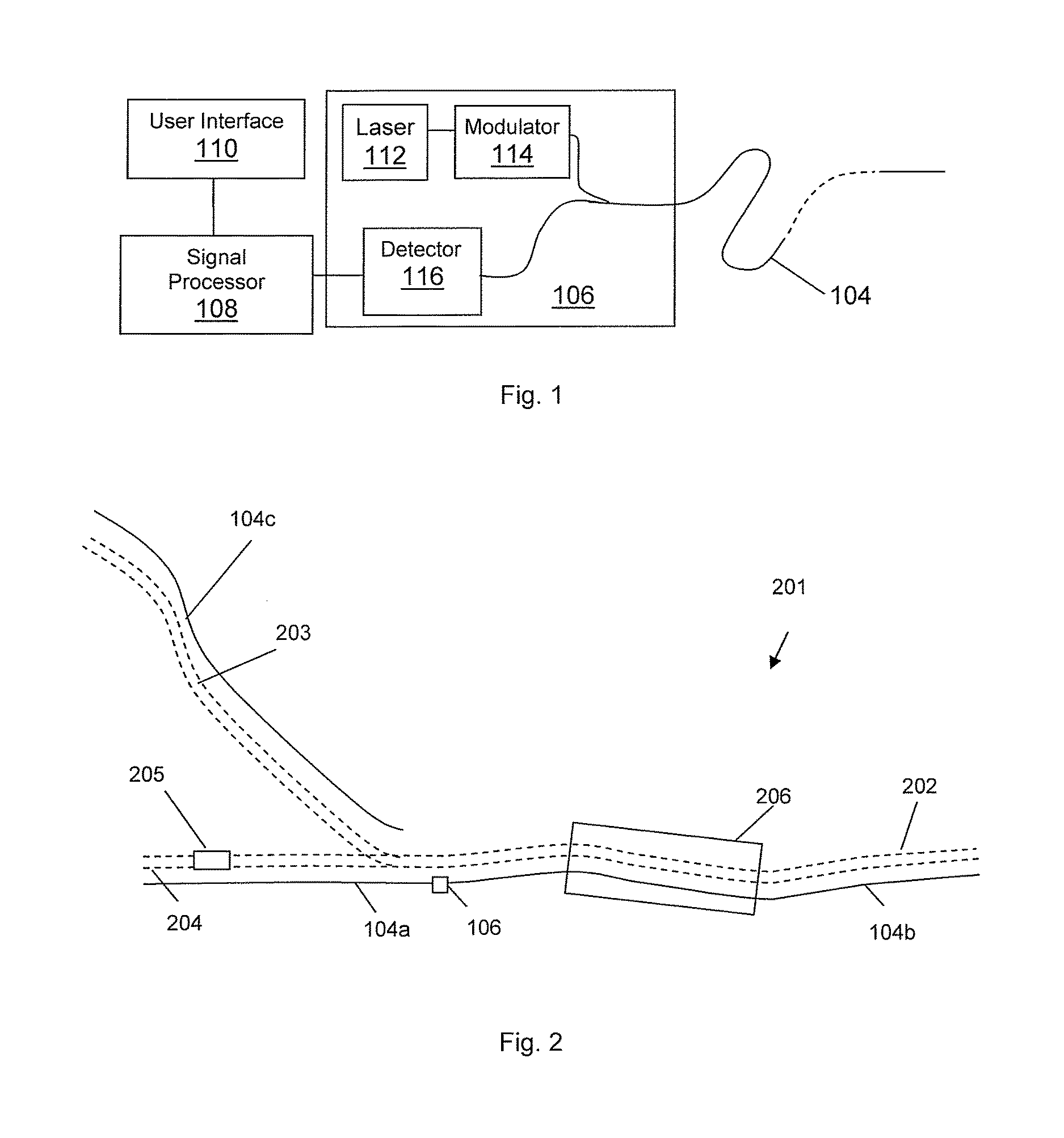
[0051]FIG. 1 shows a schematic of a distributed fibre optic sensing arrangement. A length of sensing fibre 104 is removably connected at one end to an interrogator 106. The output from interrogator 106 is passed to a signal processor 108, which may be co-located with the interrogator or may be remote therefrom, and optionally a user interface / graphical display 110, which in practice may be realised by an appropriately specified PC. The user interface may be co-located with the signal processor or may be remote therefrom.

[0052]The sensing fibre 104 can be many kilometers in length and can be, for instance 40 km or more in length. The sensing fibre may be a standard, unmodified single mode optic fibre such as is routinely used in telecommunications applications without the need for deliberately introduced reflection sites such a fibre Bragg grating or the like. The ability to use an unmodified length of standard optical fibre to provide sensing means that low cost readily available fi...


PUM


Abstract

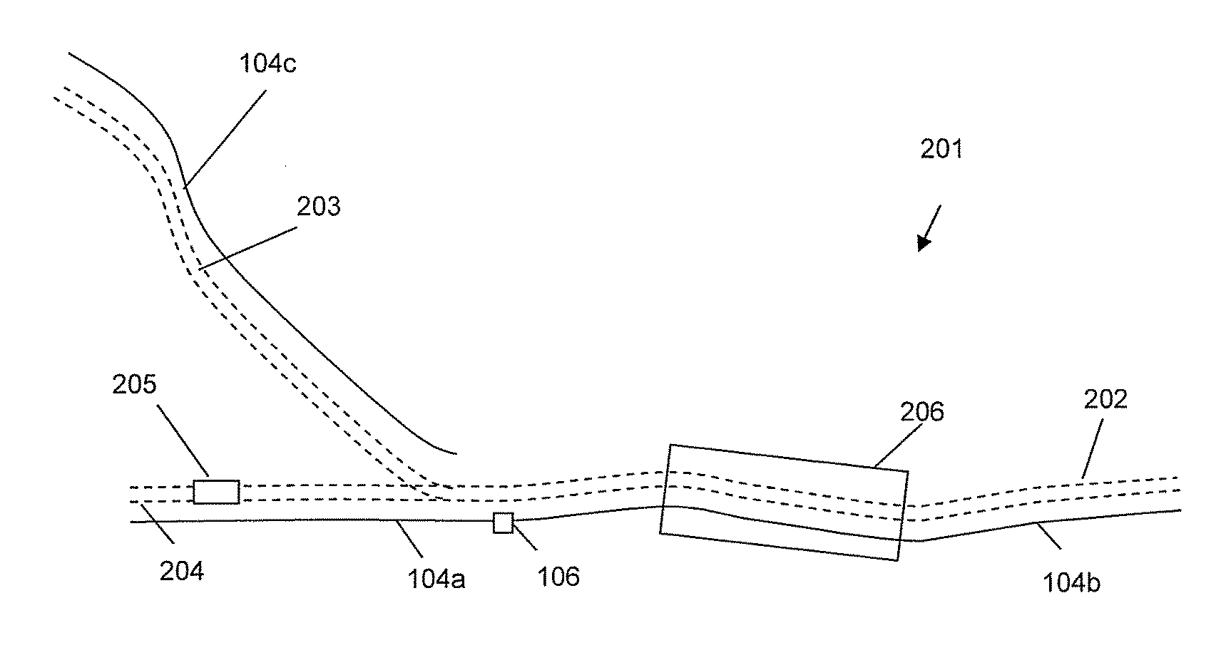
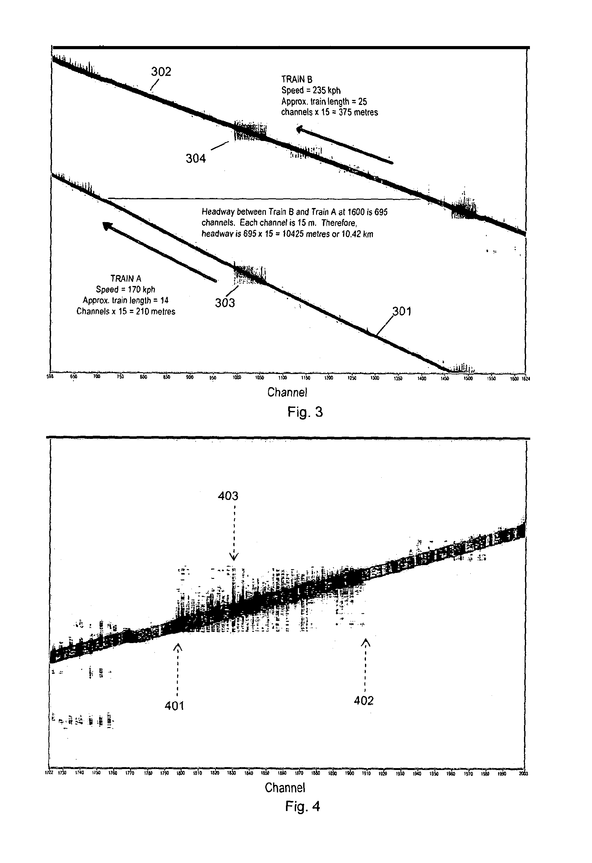
The present invention relates to conditions monitoring of structures forming part of a transport network, e.g. structural health monitoring of structures, especially tunnels by performing distributed acoustic sensing (DAS) on at least one optical fiber (104) deployed so as to monitor the structure (206) and detecting and analyzing the acoustic response to movement of traffic (205) on the network in the vicinity of the structure to detect the acoustic response (303, 304) of the structure. The acoustic response of the structure is then analyzed to detect any change in condition.

Description

FIELD OF THE INVENTION[0001]The present invention relates to monitoring of infrastructure of transport networks, for example infrastructure of rail networks, such as tunnels or bridges or the rail track itself, and in particular to condition monitoring which uses movement of traffic on the rail network.BACKGROUND OF THE INVENTION[0002]Transport network infrastructure, such as rail network infrastructure, will typically comprise some structures that it is desirable to monitor the condition of. For instance it may be desired to monitor the condition of tunnels that form part of the network to detect any faults in the tunnel that could lead to failure.[0003]In some rail networks the condition of tunnels may be manually inspected. This may comprise an inspection by suitable personnel, including a visual inspection and / or performance of various tests or measurements to identify any potential problems. For instance, the condition of the walls may be visually inspected, the relative positi...

Claims


Application Information

Patent Timeline
IPC IPC(8): G01N29/04B61L23/04B61L27/00G01M5/00B61L1/16
CPCB61L23/04B61L23/044B61L23/045B61L23/047B61L23/048B61L27/0088G01M5/0025G01M5/0033G01M5/0066G01M5/0091G01N29/04B61L1/166B61L27/53G01M5/00
Inventor GODFREY, ALASTAIR
Owner OPTASENSE HLDG LTD
Learn More