
Method of producing personalized RF coil array for MR imaging guided interventions

a technology of guided interventions and rf antennae, which is applied in the field of magnetic resonance imaging, can solve the problems that the 3d model of the surgical instrument cannot be registered with the actual anatomy of the patient, and the mr imaging-based 3d model cannot be used in the surgical procedure, so as to avoid interference between the rf antennae and the surgical instrument. , the effect of high-quality mr

Active Publication Date: 2017-03-07
KONINK PHILIPS ELECTRONICS NV
View PDF23 Cites 6 Cited by
  • Summary
  • Abstract
  • Description
  • Claims
  • Application Information

AI Technical Summary

Benefits of technology

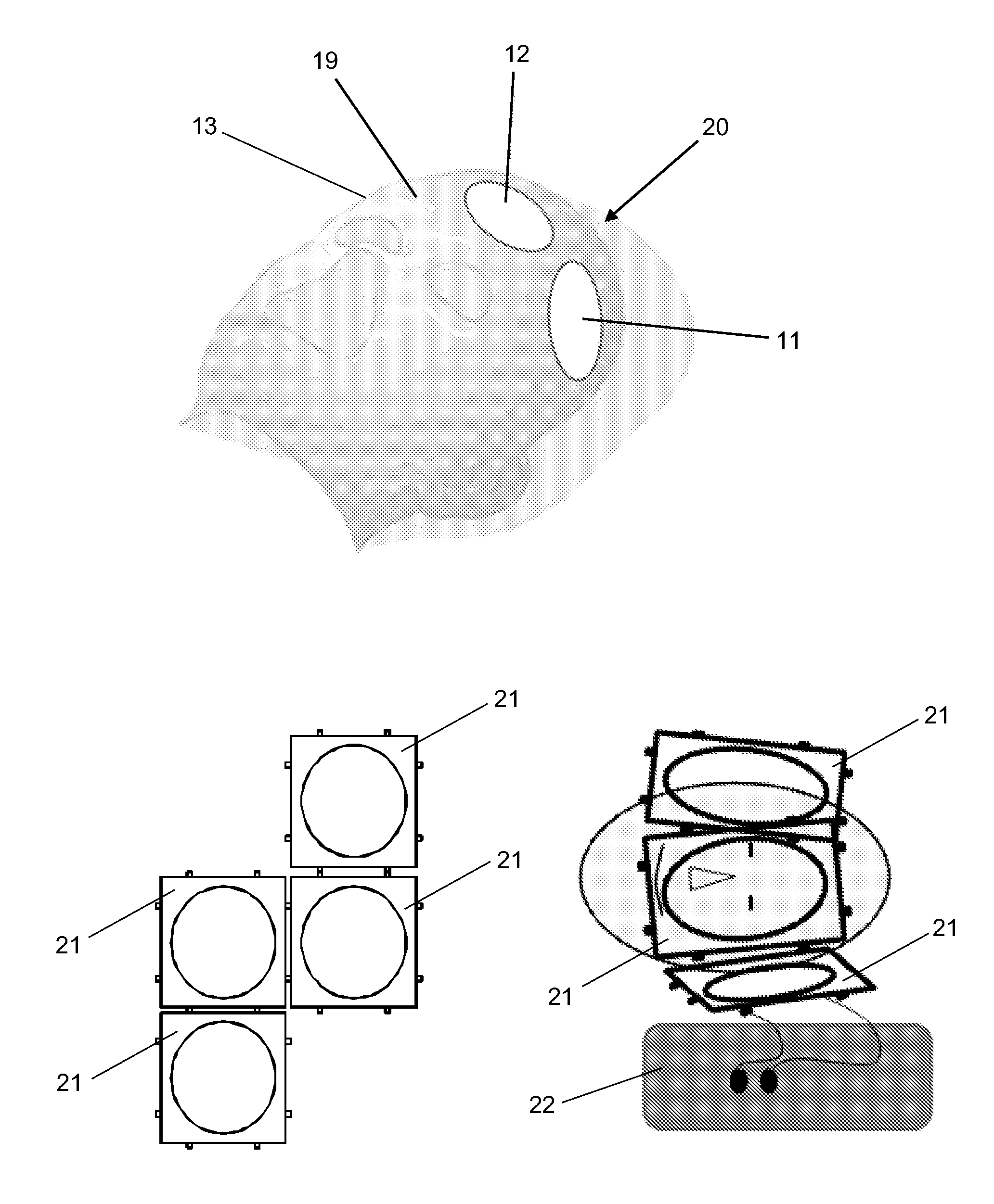
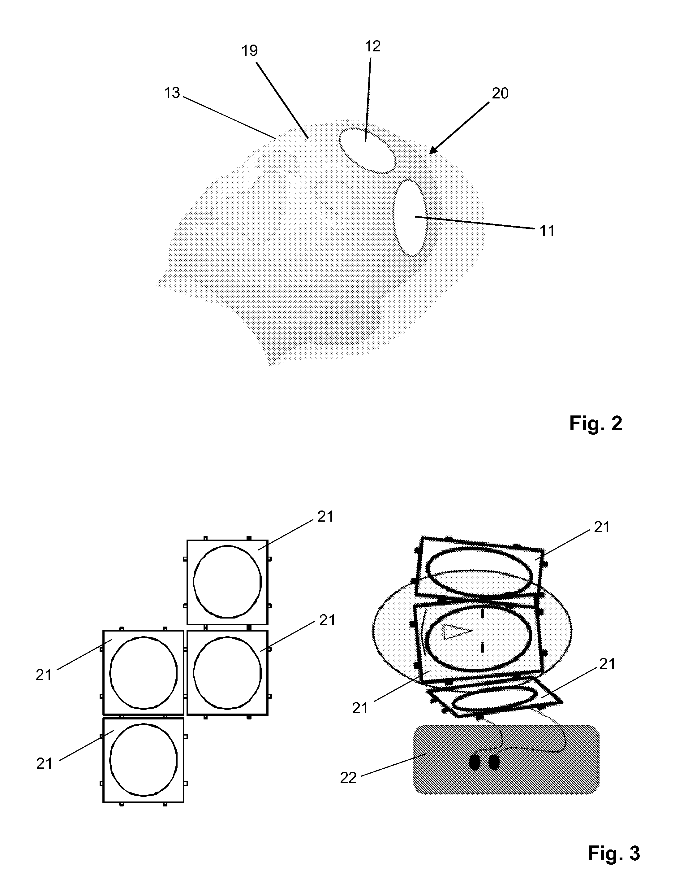
The patent text describes an improved RF coil arrangement for MR imaging guided interventions that allows for high-quality intra-operative MR imaging and good access to the patient. The optimized design of the RF coil array ensures the acquisition of high-quality MR images from both the interventional field and the access path. The substrate with the RF antennae is attached to the patient's body with one or more apertures that keep the access path clear. The use of standardized RF coil modules further facilitates the manufacturing process.

Problems solved by technology

These changes may displace organs or their tissue components to such a degree that pre-operatively acquired MR imaging-based 3D models cannot be registered with the patient's actual anatomy.
A problem is that it is difficult in a surgical setting to optimally place the RF coils required for MR signal acquisition around the respective body portion in such a fashion that (i) a good signal-to-noise ratio (SNR) is obtained and (ii) a good access to the interventional field is assured for the physician.

Method used


Image

  • Method of producing personalized RF coil array for MR imaging guided interventions
  • Method of producing personalized RF coil array for MR imaging guided interventions
  • Method of producing personalized RF coil array for MR imaging guided interventions

Examples


Embodiment Construction

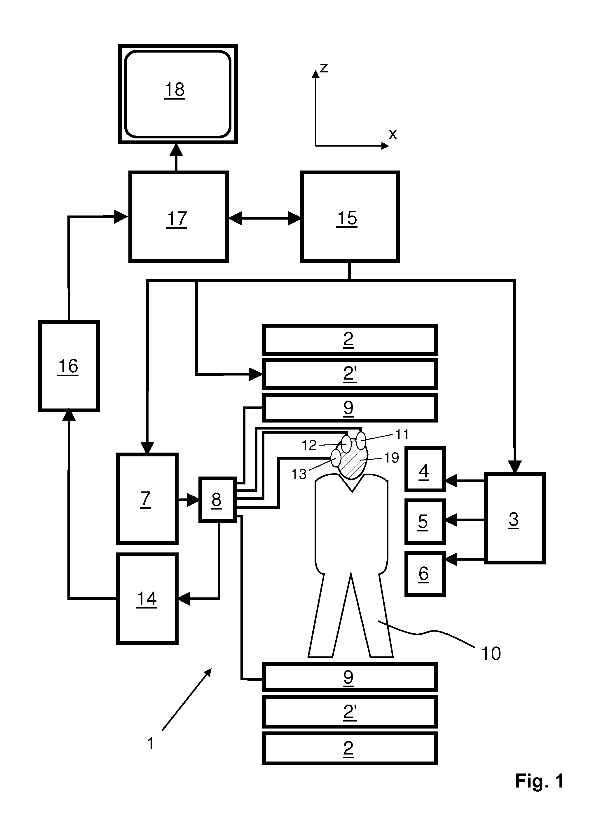
[0032]With reference to FIG. 1, a MR device 1 is shown. The device comprises superconducting or resistive main magnet coils 2 such that a substantially uniform, temporally constant main magnetic field B0 is created along a z-axis through an examination volume. The device further comprises a set of (1st, 2nd, and—where applicable—3rd order) shimming coils 2′, wherein the current flow through the individual shimming coils of the set 2′ is controllable for the purpose of minimizing B0 deviations within the examination volume.

[0033]A magnetic resonance generation and manipulation system applies a series of RF pulses and switched magnetic field gradients to invert or excite nuclear magnetic spins, induce magnetic resonance, refocus magnetic resonance, manipulate magnetic resonance, spatially and otherwise encode the magnetic resonance, saturate spins, and the like to perform MR imaging.

[0034]Most specifically, a gradient pulse amplifier 3 applies current pulses to selected ones of whole-...


PUM

PropertyMeasurementUnit
flip angleaaaaaaaaaa
radio frequencyaaaaaaaaaa
magnetic resonanceaaaaaaaaaa

Abstract

A method of manufacturing a personalized radio frequency (RF) coil array for magnetic resonance (MR) imaging guided interventions includes: acquiring diagnostic image data reflecting the anatomy of a portion of a patient's body; planning an intervention on the basis of the diagnostic image data, wherein a field of the intervention within the patient's body portion is determined; and arranging one or more RF coils on a substrate which is adapted to the patient's anatomy, in such a manner that the signal-to-noise ratio of MR signal acquisition via the one or more RF coils from the field of the intervention is optimized.

Description

CROSS-REFERENCE TO PRIOR APPLICATIONS[0001]This application is the U.S. National Phase application under 35 U.S.C. §371 of International Application No. PCT / IB2012 / 052309, filed on May 9, 2012, which claims the benefit of European Patent Application No. 11166210.2, filed on May 16, 2011. These applications are hereby incorporated by reference herein.FIELD OF THE INVENTION[0002]The invention relates to the field of magnetic resonance (MR) imaging. It concerns a method of manufacturing a personalized RF coil array for MR imaging guided interventions. Moreover, the invention relates to a computer program and to a computer workstation.[0003]Image-forming MR methods which utilize the interaction between magnetic fields and nuclear spins in order to form two-dimensional or three-dimensional images are widely used nowadays, notably in the field of medical diagnostics, because for the imaging of soft tissue they are superior to other imaging methods in many respects, do not require ionizing...

Claims


Application Information

Patent Timeline
Patent Type & Authority Patents(United States)
IPC IPC(8): A61B5/05H01F41/04G01R33/34A61B5/055G06F17/50H01F3/02B29C67/00
CPCA61B5/055A61B34/20B29C67/0088G01R33/34007G01R33/34084G06F17/50H01F3/02H01F41/04A61B2090/374Y10T29/49018Y10T29/49069Y10T29/49073Y10T29/49075Y10T29/532A61B2034/2065G06F30/00
Inventor MARTENS, HUBERT CECILE FRANCOISMOORE, ELIZABETH ANNEPOSSANZINI, CELILIANIJENHUIS, MARCO HUBERTUS JOHANNESPARDOEL, MICHEL GERARDUSBOS, CLEMENSELEVELT, AALDERT JANWIRTZ, DANIEL
Owner KONINK PHILIPS ELECTRONICS NV
Learn More