Piston for an axial piston machine

a piston machine and axial piston technology, applied in mechanical equipment, pumps, liquid fuel engines, etc., can solve the problems of thermal problems at the contact surfaces between pistons and cylinders, problems such as the strength of the piston retaining means, and the inability to manufacture, etc., to achieve the effect of being sufficiently stable and easy to manufactur

Active Publication Date: 2017-03-14
LIEBHERR MACHINES BULLE
View PDF18 Cites 3 Cited by
  • Summary
  • Abstract
  • Description
  • Claims
  • Application Information

AI Technical Summary

Benefits of technology

[0008]It is one object of the present invention to provide a piston for an axial piston machine that unites the advantages of a solid piston and a hollow piston, is easy to manufacture, and is sufficiently stable.
[0013]In a preferred embodiment, the chambers are formed to be hollow and cylindrical. This facilitates the manufacture of the chambers. The base area, for example, can be circular, kidney-shaped, polygonal, or oval.
[0016]Alternatively, the piston body can include a middle part which is connected with a base part. Preferably, the chambers are arranged in the middle part. In a particularly preferred embodiment, only the middle part includes chambers. The provision of the chambers by the middle part allows less expensive manufacturing of the piston body.
[0044]Since the webs left between the chambers inside this ring-shaped arrangement of the chambers extend radially and axially, the piston is stabilized considerably.

Problems solved by technology

At increased speeds, strength problems arise for the cylinders due to large centrifugal forces, and due to the large mass forces strength, problems arise for the piston retaining means.
Furthermore, thermal problems can arise at the contact surfaces between piston and cylinders, as high frictional forces result from the centrifugal forces.
However, this has the disadvantage that the cavity forms a dead space which is compressed and then decompressed again at each piston stroke.
The non-negligible compressibility of the hydraulic fluid leads to a deterioration of the efficiency.
Such a piston design however, can lead to problems during friction welding, which is usually employed for mounting the closure, since the central column is greatly loaded.
In addition, the manufacture of the annular cavity by extrusion is expensive.
However, this in turn requires an expensive design of the piston wall and in addition leads to stability problems with the piston.
There also exists a complicated manufacturing method for the piston, without sufficient stability of the piston being ensured.

Method used


Image

  • Piston for an axial piston machine
  • Piston for an axial piston machine
  • Piston for an axial piston machine

Examples


Embodiment Construction

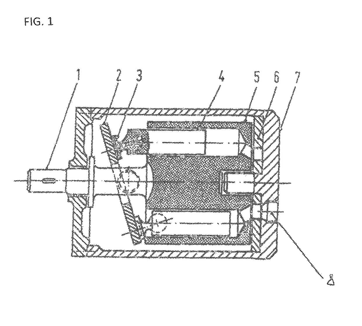
[0071]FIG. 1 shows an exemplary embodiment of an axial piston machine according to the invention, in which the pistons according to the invention are used.

[0072]The exemplary embodiment relates to a swash plate machine in which the cylinder block 5 is non-rotatably connected with the drive shaft 1. The swash plate 2 is non-rotatably connected with the housing 7, i.e. it cannot rotate with the same. Since the exemplary embodiment relates to an adjustable machine, the same is pivotally mounted at the housing. The piston 4 supports on the swash plate 2. The control disk 6 likewise is non-rotatably connected with the housing 7 and is connected with the pressure line 8.

[0073]When the drive shaft 1 and with the same the cylinder block 5 are rotated, the pistons perform a stroke movement. Due to a corresponding design of the control openings in the control disk 6, the same are alternately connected with the high-pressure side and the low-pressure side. By applying a sufficient oil pressure...


PUM

PropertyMeasurementUnit
pressureaaaaaaaaaa
speedsaaaaaaaaaa
strengthaaaaaaaaaa

Abstract

A piston for an axial machine includes a piston body having a cavity that is closed in a pressure-tight way. The cavity is divided into a plurality of chambers, arranged one beside the other in cross-section.

Description

CROSS REFERENCE TO RELATED APPLICATION[0001]This application claims priority under 35 U.S.C. §119 to application no. 00661 / 13, filed Mar. 25, 2013, in Switzerland, the entire disclosure of which is expressly incorporated herein by reference.BACKGROUND OF THE INVENTION[0002]The present invention relates to a piston for an axial piston machine. The piston can be a piston for an axial piston machine with a swash plate design or a wobble plate design.[0003]In known axial piston machines solid pistons, which set limits on an operation with higher speeds, are used. At increased speeds, strength problems arise for the cylinders due to large centrifugal forces, and due to the large mass forces strength, problems arise for the piston retaining means. Furthermore, thermal problems can arise at the contact surfaces between piston and cylinders, as high frictional forces result from the centrifugal forces.[0004]As an alternative to solid pistons, hollow pistons therefore are used, in order to o...

Claims


Application Information

Patent Timeline
Patent Type & Authority Patents(United States)
IPC IPC(8): F16J1/00F04B1/12F03C1/28F04B53/14F01B3/00
CPCF16J1/00F01B3/0085F03C1/0605F04B1/124F04B53/14Y10T29/49249
Inventor BAERISWYL, MARIOFEUSI, ERWIN
Owner LIEBHERR MACHINES BULLE
Why Eureka
Try Eureka