
Energy storage system of uninterruptible power supply equipped with battery and method of driving the same

a technology of energy storage system and battery, which is applied in emergency power supply arrangements, climate sustainability, ac network load balancing, etc., can solve the problems of requiring a lot of recovery time, affecting the efficiency of energy storage, so as to reduce power consumption, improve productivity, and be more economical

Active Publication Date: 2017-03-28
EHWA TECH INFORMATION
View PDF7 Cites 5 Cited by
  • Summary
  • Abstract
  • Description
  • Claims
  • Application Information

AI Technical Summary

Benefits of technology

The present invention is aimed at solving problems in energy storage systems of UPSs by reducing power consumption, increasing battery efficiency, and effectively managing demand and power bills. The technical effects of the invention include reusing energy, reducing power consumption, providing users with profit, improving productivity, and controlling discharging power to increase battery efficiency. The invention also handles demand management and power bill management effectively even when a commercial power source is normal.

Problems solved by technology

A lead battery is problematic in terms of inspection and management, such as ineffective handling in emergency, because the activation of a chemical substance that forms the battery, the terminal voltage irregularity of the battery, and a change in the generation of corrosion of the terminal unit are not checked.
Although a momentary power failure occurs, a UPS is inevitably used in a computer server and production equipment that require a lot of time taken for recovery in order to prepare for the momentary power failure.
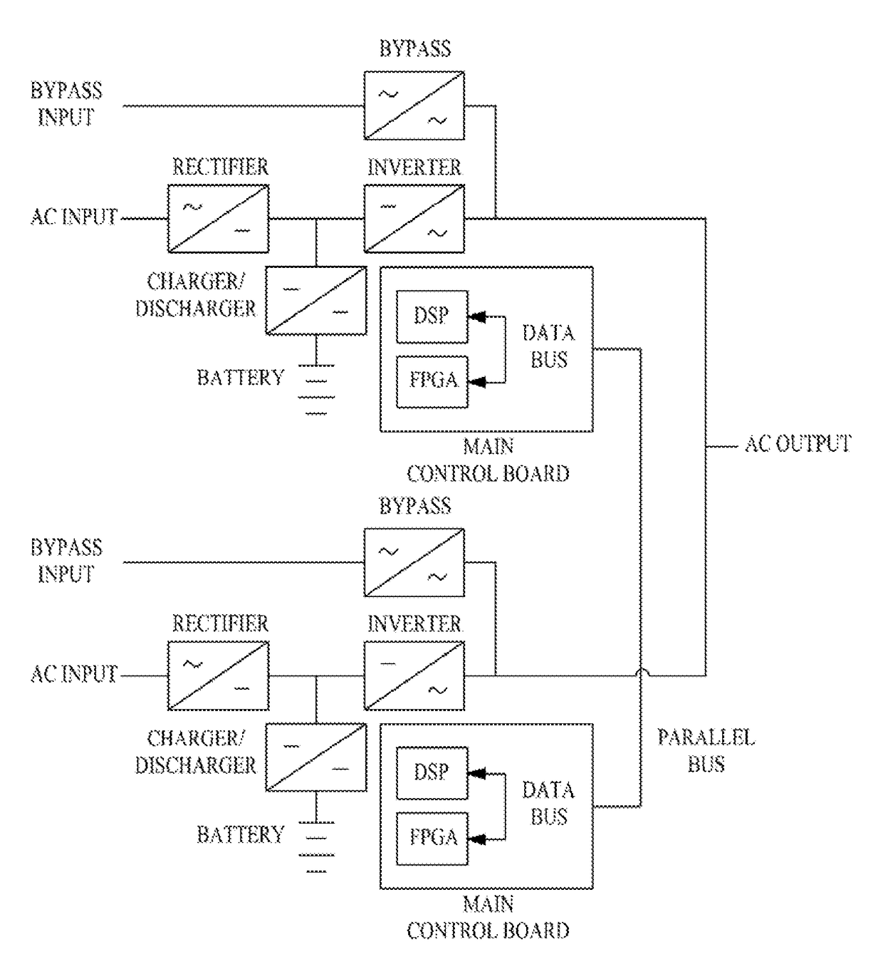
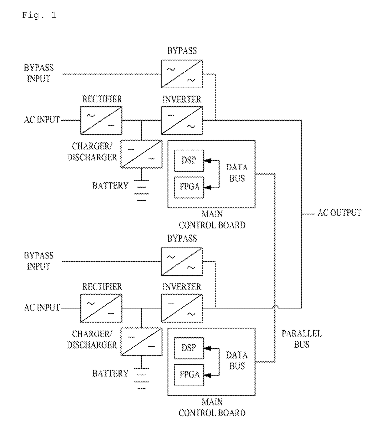
However, the aforementioned prior arts do not disclose technology in which the battery is used as energy more efficiently in a UPS basically including a rectifier (or a converter), a charging / discharging unit (or a bidirectional converter), an inverter, a bypass, a control board, and the battery.

Method used


Image

  • Energy storage system of uninterruptible power supply equipped with battery and method of driving the same
  • Energy storage system of uninterruptible power supply equipped with battery and method of driving the same
  • Energy storage system of uninterruptible power supply equipped with battery and method of driving the same

Examples


Embodiment Construction

[0042]The above objects, other objects, and new characteristics of the present invention will become more apparent by technology disclosed in the specification and the accompanying drawings.

[0043]First, a relationship between a UPS to which the present invention is applied and the battery included in the UPS is described below.

[0044]The battery capacity of the UPS is determined according to the setting of a maximum discharging time.

[0045]The discharging current of a UPS for single phase and 3-phase output is identically calculated and determined by a UPS capacity and the battery use voltage. A discharging current Id is calculated as in Equation 1 based on a UPS of 100 KVA.

[0046]Id=100⁢⁢KVA×0.8⁢⁢(load⁢⁢factor)1.75⁢⁢(final⁢⁢voltage)×240⁢⁢(number⁢⁢of⁢⁢cells)×0.96⁢⁢(inverter⁢⁢efficiency)=198⁢⁢A(1)

[0047]In Equation 1, assuming that the power failure compensation time of the UPS is 30 minutes and a lead battery is used according to Equation 1, a use capacity is a 2 V 250 AH 240 cells acco...


PUM


Abstract

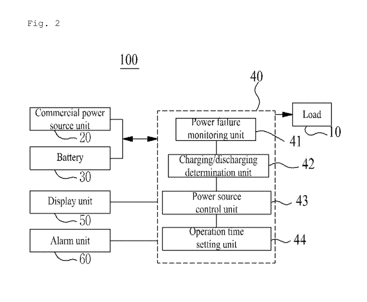
Disclosed herein are the energy storage system of an Uninterruptible Power Supply (UPS) equipped with the battery and a method of driving the same. The energy storage system includes a commercial power source unit configured to supply a first power source to a load, and the battery configured to supply a second power source to the load. And the system monitors a power failure state in the commercial power source unit, determines a charging state of the battery, and controls the commercial power source unit and the battery in response to output of monitoring or determination, so that the first power source or the second power source is supplied to the load. A power reservation ratio for the use of power can be increased by reducing power used during daytime.

Description

CROSS REFERENCE TO RELATED APPLICATION[0001]The present application claims the benefit of Korean Patent Application No. 10-2013-0090288 filed in the Korean Intellectual Property Office on Jul. 30, 2013, the entire contents of which are incorporated herein by reference.BACKGROUND OF THE INVENTION[0002]1. Technical Field[0003]The present invention relates to the energy storage system of an Uninterruptible Power Supply (UPS) equipped with the battery and a method of driving the same and, more particularly, to the energy storage system of a UPS equipped with the battery, wherein some capacity of the battery is used as an energy source by controlling the discharge power of the battery using a rectifier and a bidirectional converter used in the UPS, thereby being capable of reducing the consumption power of a user and using the remaining capacity as reserved power in emergency, and a method of driving the same.[0004]2. Description of the Related Art[0005]Recently, an energy storage system...

Claims


Application Information

Patent Timeline
Patent Type & Authority Patents(United States)
IPC IPC(8): H02J3/00H02J3/32H02J9/06
CPCH02J3/00H02J3/32H02J9/062Y10T307/344H02J2310/12Y04S20/20Y02B70/30H02J9/06
Inventor CHUNG, SUNG WONLEE, KYUNG SUKYUM, DONG HUN
Owner EHWA TECH INFORMATION
Learn More