Handling system and method of operating a handling system

a technology of handling system and handling head, which is applied in the field of handling system, can solve the problems of time-consuming process inputs or extensive programming steps

Active Publication Date: 2017-04-11
J SCHMALZ GMBH
View PDF8 Cites 1 Cited by
  • Summary
  • Abstract
  • Description
  • Claims
  • Application Information

AI Technical Summary

Benefits of technology

[0012]The system can have extended flexibly without expensive re-programming or data maintenance being necessary.
[0013]During operation, an optimization of the stored operational data can be carried out (for example, the vacuum generator can determine optimized operating parameters and store them in the recognition unit). The recognition unit then has constantly-saved updated operating data which are available immediately for a change or a further expansion of the device. When changing the handling device or an expansion of the device, one can thus significantly shorten the break-in required. Because the operating data is individually assigned to the handling device, an error in a complex system can be easily assigned to a particular functional unit. In addition, the operating data can contain information about individual tightness of the handler, load capacity, or service life, and provide a kind of individual resume. So, for example, a planned maintenance can be carried out on the individual handling devices.
[0016]The recognition unit and the vacuum handling device may be mechanically interconnected, for example, as a structural unit. In particular, the detection unit may be arranged on a unit case of the vacuum handling device, for example combined into one module. The structural unit (including the detection unit and the vacuum handling device) may advantageously be releasable connected to the vacuum generator (for example, with a suitable releasable bracket). In particular, the structural unit (including the detecting unit and the vacuum handling device) may be configured so as to be plugged into and subsequently released from the vacuum generator (advantageously so as to be exchangeable). This enables a flexible conversion.
[0022]The system may be a bus system (for example, a field bus) via which the vacuum generator is connected to the central control device. The recognition units can also be connected to the bus system and can refer to suitable bus communication devices. A bus-based design allows for easy expansion of the system to further handling spaces.
[0025]Reading the operating data may be done after changing or newly installing a handling device to the system. Subsequently, the system can be put back into service without costly reconfiguration. After the reading, a sub-control unit of the vacuum generator determines the revised and optimized operating data that it re-transfers directly to the detection unit and stores it there. In this respect, the vacuum generator can perform an optimization process and save optimized data back to the detection unit.

Problems solved by technology

This may require extensive programming steps or time-consuming process inputs.
In addition, when a new handling device is added, a break-in period for the system is typically necessary to verify (and, if necessary, optimize) the operating parameters.

Method used


Image

  • Handling system and method of operating a handling system
  • Handling system and method of operating a handling system

Examples


Embodiment Construction

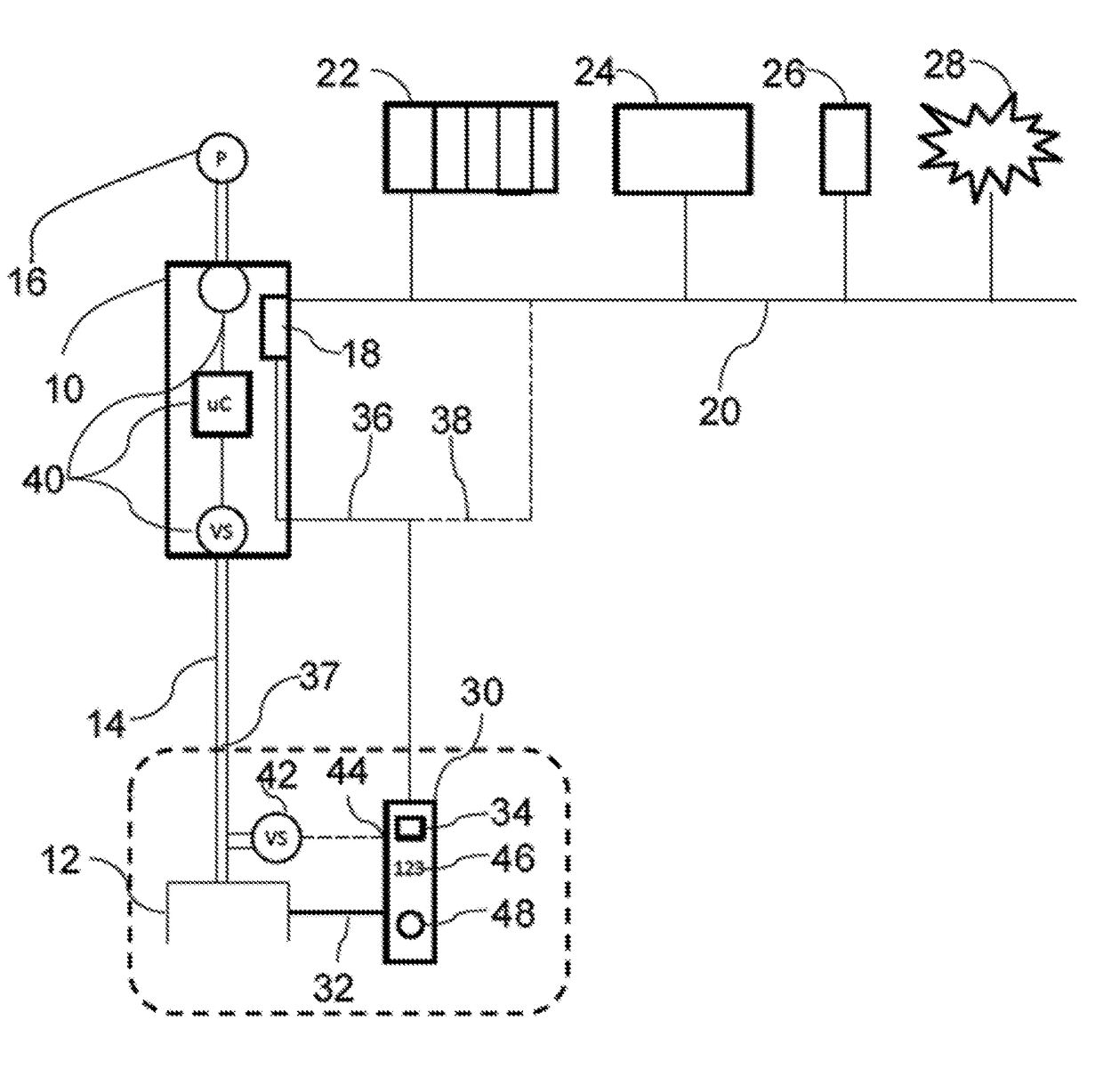
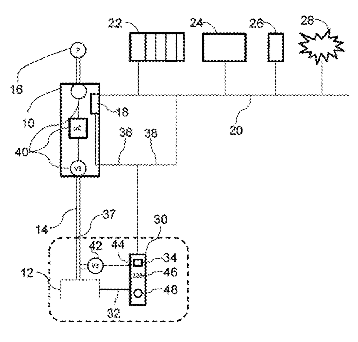
[0030]Further details of the invention will be described in greater detail below with reference to the accompanying figures. FIG. 1 shows a handling system with a vacuum generator 10 and an operating unit. In the example shown in FIG. 1, the operating unit is a vacuum gripper's formed vacuum handling device 12, which is pressure connected over a vacuum line 14 to a vacuum outlet of the vacuum generator 10. In one embodiment, the vacuum generator 10 may be formed as an ejector driven by compressed air supply 16. The system may advantageously include a plurality of vacuum generators connected to associated vacuum handling devices.

[0031]The vacuum generator 10 has a sub-control unit 18 which controls the operating state of the vacuum generator 10. The vacuum generator 10 or its sub-control unit 18 is connected to a field bus 20, to which other vacuum generators may also be connected. The field bus 20 is connected to a central control device 22 which can properly control the vacuum gene...


PUM


Abstract

A handling system having at least one vacuum generator and an associated vacuum handling device connected to and operable via the vacuum generator. The vacuum handling device is provided with an individually assigned recognition unit including a memory device in which operating data for the vacuum handling device is storable and can be read out. Each vacuum generator has a respective sub-control unit adapted to control the vacuum generator depending on data transmitted from the recognition unit. The memory device of the recognition unit can be read out directly from the sub-control unit.

Description

CROSS-REFERENCE TO RELATED APPLICATION[0001]This application is based upon and claims priority to German Patent Application No. DE 102014206308.6, filed on Apr. 2, 2014.BACKGROUND OF THE INVENTION[0002]1. Field of the Invention[0003]The present invention relates, generally, to handling systems used such as in production or processing lines and, more specifically, to a handling system for handling and / or for the further transport of workpieces.[0004]2. Description of the Related Art[0005]Handling systems known in the related art are typically built of several functional units, in particular one or more vacuum generators and operated vacuum handling devices. In operation, the individual functional units need to be coordinated with one another. Thus, operating parameters of the handling apparatus, for example, need to known in order to facilitate control in accordance with the vacuum generator. As is known in the related art, vacuum production needs to be connected to a bus system whic...

Claims


Application Information

Patent Timeline
Patent Type & Authority Patents(United States)
IPC IPC(8): B25J15/06B25J15/04B25J19/02
CPCB25J15/0616B25J15/0483B25J15/0675B25J19/02
Inventor HOLECEK, THOMASDUNKMANN, WALTER
Owner J SCHMALZ GMBH
Why Eureka
Try Eureka