Coolant control valve of engine

a technology of control valve and engine, which is applied in the direction of multiple way valve, machine/engine, mechanical apparatus, etc., can solve the problems of deteriorating operation, fuel consumption increase, and deteriorating quality of exhaust gas, and achieve the effect of enhancing a characteristic of the por

Active Publication Date: 2017-04-11
HYUNDAI MOTOR CO LTD +1
View PDF17 Cites 9 Cited by
  • Summary
  • Abstract
  • Description
  • Claims
  • Application Information

AI Technical Summary

Benefits of technology

[0011]Various aspects of the present invention are directed to providing a coolant control valve of an engine while maintaining its entire size to be small by enhancing a characteristic of a port through which a coolant flows in and respectively controlling the coolant flowing to the left and right of the engine.
[0018]A curved surface having a predetermined curvature radius for smooth inflow of the coolant may be formed at an edge where the second inlet is formed in the outer surface of the cylindrical valve.
[0021]According to the present invention, the first inflow pipe and the second inflow pipe are additionally provided to increase a degree of freedom in design, reduce flow resistance of the coolant of the engine having the left and right cylinder heads and the left and right cylinder banks, and separately control the coolant.
[0022]In addition, the second inflow pipe is connected with the recess portion formed between the first convex surface and the second convex surface, and the flow resistance is reduced by forming the second inlet in the cylindrical valve corresponding to the recess portion, and the coolant can be more stably circulated.

Problems solved by technology

When a coolant temperature of the engine is low, viscosity of the oil is increased so that a frictional force is increased, fuel consumption is increased, and a temperature of an exhaust gas is slowly increased so that time for activation of a catalyst is extended, and accordingly, quality of the exhaust gas may be deteriorated.
Furthermore, time for normalization of operation of the heater is extended so that a passenger or a driver may feel cold.
When the coolant temperature of the engine is excessively high, knocking occurs, and ignition timing needs to be adjusted for suppression of the occurrence of knocking, thereby causing operation deterioration.
In addition, when a temperature of lubricant is excessively high, lubrication performance may be deteriorated.
In particular, a flow path of the coolant is complex because left and right cylinder heads and left and right cylinder banks are separately cooled, and thus studies on an integrated flow control valve that can respectively control the cylinder heads and the cylinder banks are continuing.

Method used


Image

  • Coolant control valve of engine
  • Coolant control valve of engine
  • Coolant control valve of engine

Examples


Embodiment Construction

[0030]Reference will now be made in detail to various embodiments of the present invention(s), examples of which are illustrated in the accompanying drawings and described below. While the invention(s) will be described in conjunction with exemplary embodiments, it will be understood that the present description is not intended to limit the invention(s) to those exemplary embodiments. On the contrary, the invention(s) is / are intended to cover not only the exemplary embodiments, but also various alternatives, modifications, equivalents and other embodiments, which may be included within the spirit and scope of the invention as defined by the appended claims.

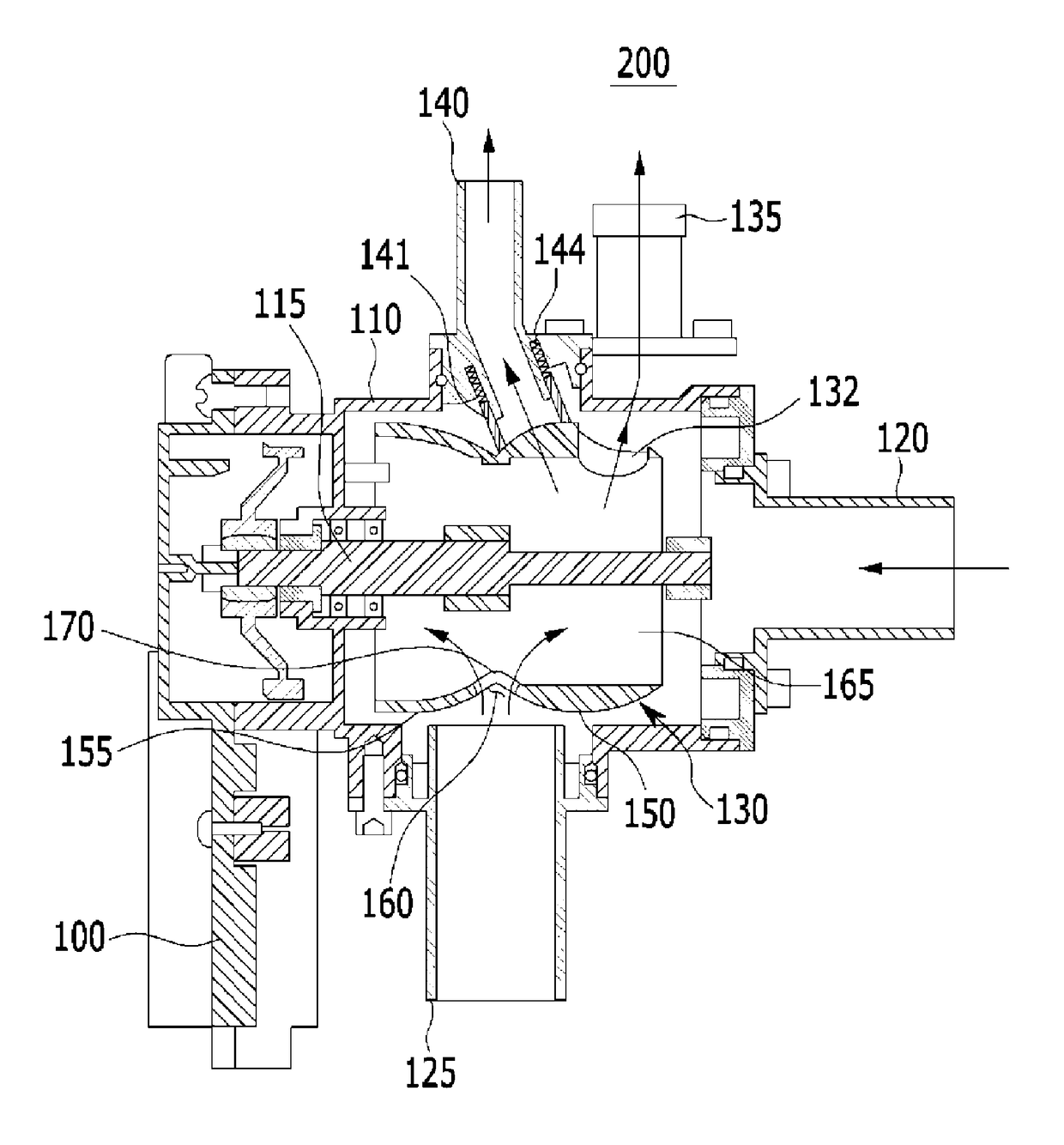
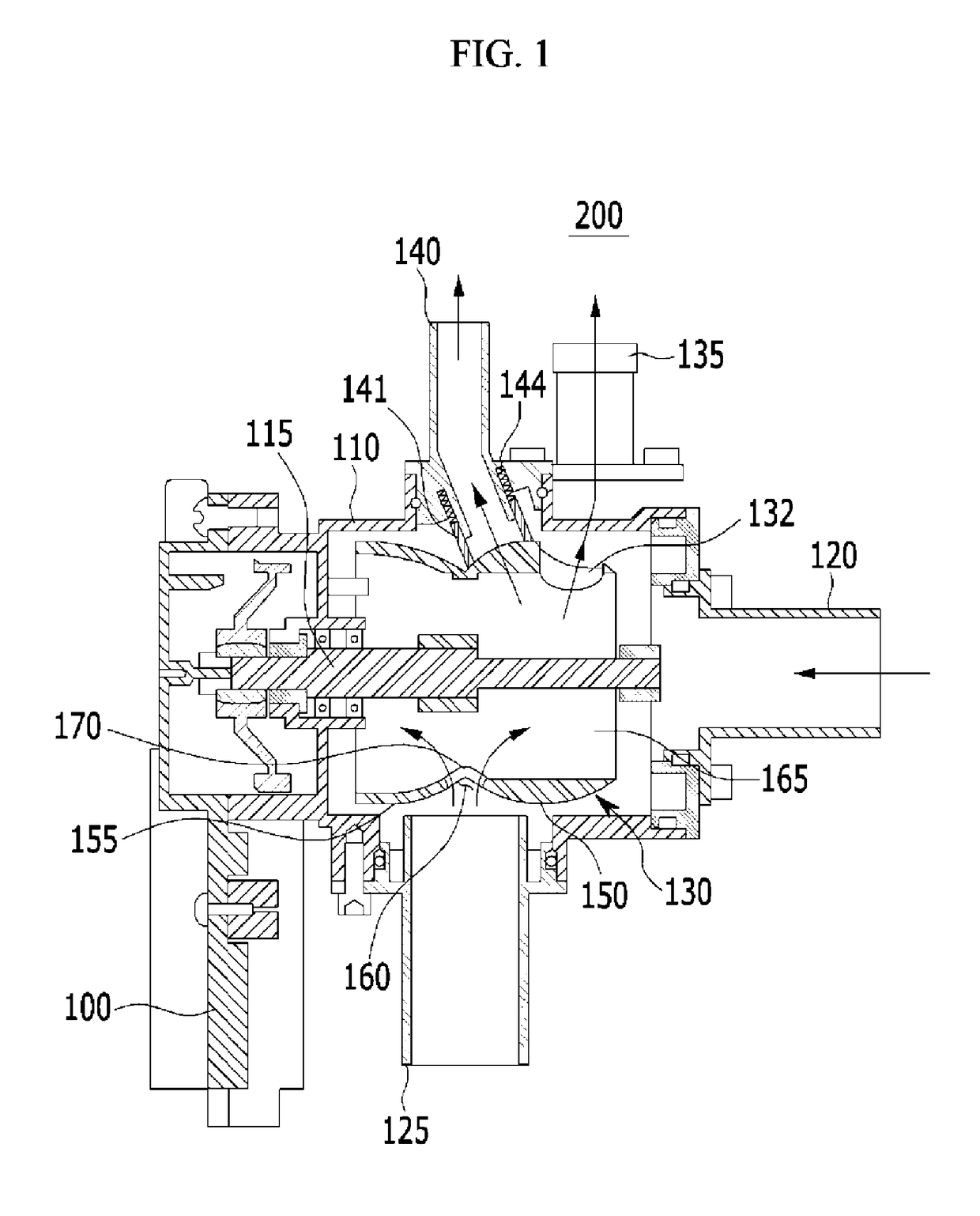
[0031]FIG. 1 is an overall cross-sectional view of a coolant control valve of an engine according to various embodiments of the present invention.

[0032]Referring to FIG. 1, a control valve of an engine includes a motor housing 100, a rotation load 115, a cylindrical valve 130, a valve housing 110, a first inflow pipe 120, a second...


PUM


Abstract

A coolant control valve of an engine may include a cylindrical valve in which a space is formed along a length directional center axis thereof, a first inlet through which a coolant flows being formed at one end of the cylindrical valve, an outlet being formed at an outer surface of the cylindrical valve in the space, a first convex surface and a second convex surface and a second inlet through which the coolant flows into the space being formed at the outer surface corresponding to a recess portion formed between the first convex surface and the second convex surface, a valve housing, a first inflow pipe transmitting the coolant to the space through the first inlet, a second inflow pipe transmitting the coolant to the space through the second inlet, and a driver provided at one side of the valve housing to rotate the cylindrical valve.

Description

CROSS-REFERENCE TO RELATED APPLICATION[0001]The present application claims priority to Korean Patent Application No. 10-2014-0084942 filed Jul. 8, 2014, the entire contents of which is incorporated herein for all purposes by this reference.BACKGROUND OF THE INVENTION[0002]Field of the Invention[0003]The present invention relates to a coolant control valve of an engine, controlling coolants for a cylinder head, a bank of cylinder, a radiator, a throttle body, a heater, an automatic transmission fluid warmer, and the like for improving cooling efficiency and reducing fuel consumption.[0004]Description of Related Art[0005]An engine generates rotation force from combustion of fuel, and the remaining energy from the combustion of the fuel is exhausted as heat energy. In particular, a coolant absorbs heat energy while circulating through the engine, a heater, and a radiator, and discharges the absorbed heat energy to the outside.[0006]When a coolant temperature of the engine is low, visco...

Claims


Application Information

Patent Timeline
Patent Type & Authority Patents(United States)
IPC IPC(8): F16K11/00F01P3/20F01P7/14F16K11/087
CPCF01P7/14F01P3/20F16K11/0876
Inventor LEE, PHILGI
Owner HYUNDAI MOTOR CO LTD
Why Eureka
Try Eureka