High speed, low noise, low inductance transmission line cable

a transmission line and low noise technology, applied in the field of cables, can solve the problems of increasing frequency selective loss, none of the above-mentioned solutions have proven to be both highly effective and practical to implement in a wide range of applications, and its application is somewhat limited, so as to reduce signal attenuation, minimize noise generation, and increase mutual inductance

Active Publication Date: 2017-04-11
WIREWORLD BY DAVID SALZ
View PDF19 Cites 15 Cited by
  • Summary
  • Abstract
  • Description
  • Claims
  • Application Information

AI Technical Summary

Benefits of technology

[0019]The present invention relates to transmission cable designs that utilize novel conductors consisting of two or more solid metallic strands laid adjacent to one another in a flat parallel configuration within an extruded insulator. Groups of these flat conductors are stacked and twisted together to form structures that are both stable and flexible. The stacked configuration increases the mutual inductance between the signal conductor(s) and the shield conductor(s), thus reducing the signal attenuation caused by inductive reactance. The shield conductors may be covered with conductive plastic to minimize noise generation while providing an electrical connection to the shield.

Problems solved by technology

The challenge of those designs is to overcome the inherent tendency of thick cylindrical conductors to increase inductive reactance while creating additional frequency selective loss due to ‘skin effect’.
While previous low-inductance cable designs have provided some improvements over conventional cables, none have proven to be both highly effective and practical to implement in a wide range of applications.
The audio cable disclosed by Poulsen in U.S. Pat. No. 6,225,563 provides the signal transmission advantages of low inductance, but its applications are somewhat limited by its use of extremely thin ribbon conductors, which are fragile and require the use of special handling and termination procedures.
Another embodiment disclosed in by Goertz utilizes stranded conductors, but it fails to provide any effective means for stabilizing the conductors when the cable is flexed.
Cables also degrade the fidelity of signal transmission by introducing noise.
In addition to externally induced noise, or electromagnetic interference (“EMI”), cables contaminate electrical signals with triboelectric noise, which is generated by movement, intermittent contact and localized charge / discharge effects between the conductors and insulation.
In addition to the signal attenuation and triboelectric noise problems mentioned above, the performance of high-speed digital signal cables can be limited by several additional factors, including impedance uniformity, crosstalk, and skew.
The degree of waveform attenuation and distortion introduced by a digital signal cable has a direct influence on the number of data errors produced by the receiving device.
Despite that distinct advantage over single-conductor cables, differential cables are nonetheless subject to a variety of limitations that can distort and contaminate both analog and digital signals.
If one side of a differential signal arrives significantly ahead of the other side, the resulting waveform will be distorted.
Skew can be caused by impedance variations or differences in the length of the conductors or conductor pairs.
Furthermore, a net difference in the impedance of the two conductors of a differential pair can also cause a skew error.
The single flattened wire design, however, not only adds specialized procedures to the manufacturing process, it creates a cable structure that is inherent more stiff, which would be a distinct disadvantage in speaker cable applications where flexibility and ease of termination are required.
The use of a conventional braided or served shield over each of the balanced pairs would negate most of the advantages of the design because of the inductive nature of those shields.
There is no teaching in Nair or Clark, however, to use standard round strands that do not require additional manufacturing and that retain flexibility in the cable to create wires that are flat, rectangular or any other geometric shape.

Method used


Image

  • High speed, low noise, low inductance transmission line cable
  • High speed, low noise, low inductance transmission line cable
  • High speed, low noise, low inductance transmission line cable

Examples


Embodiment Construction

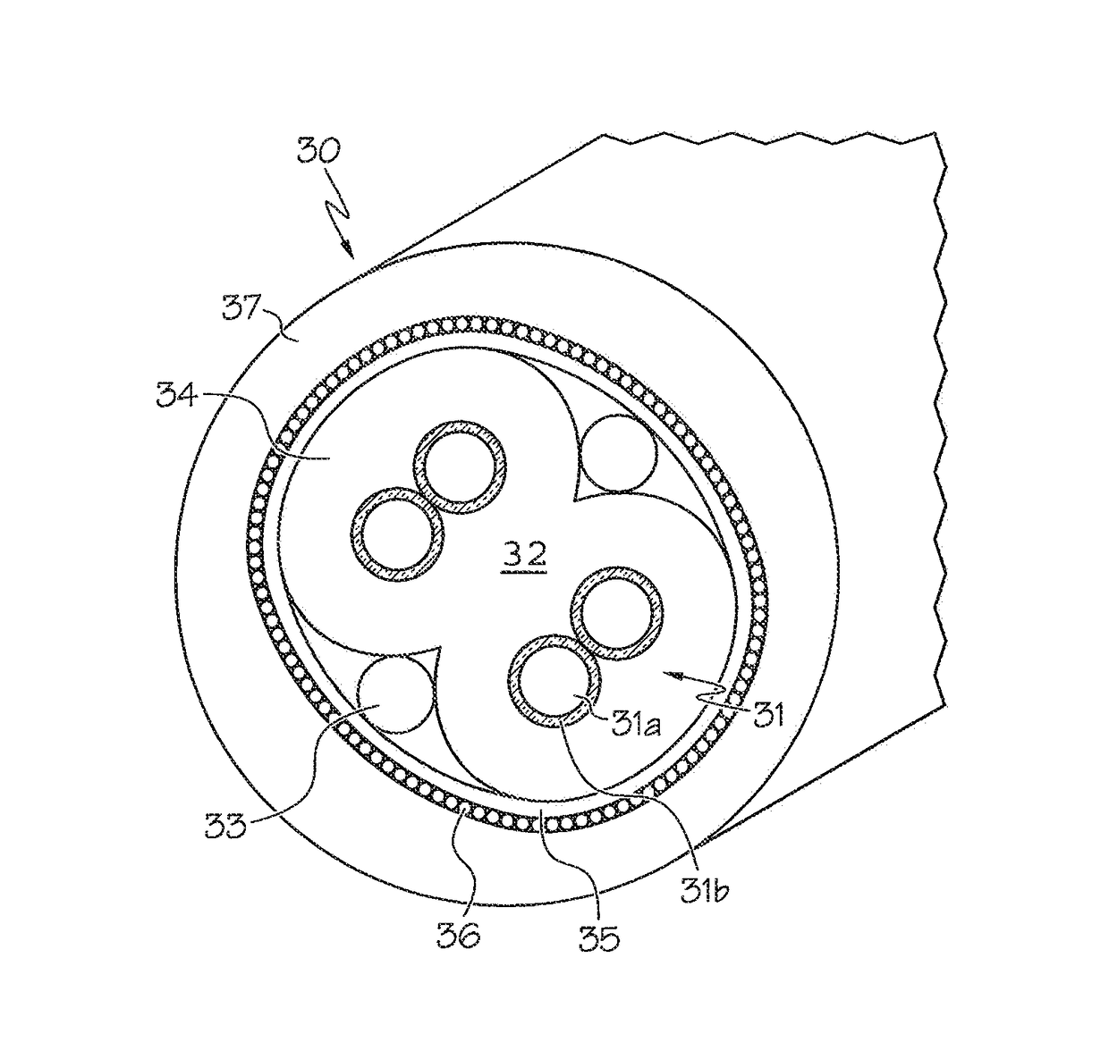
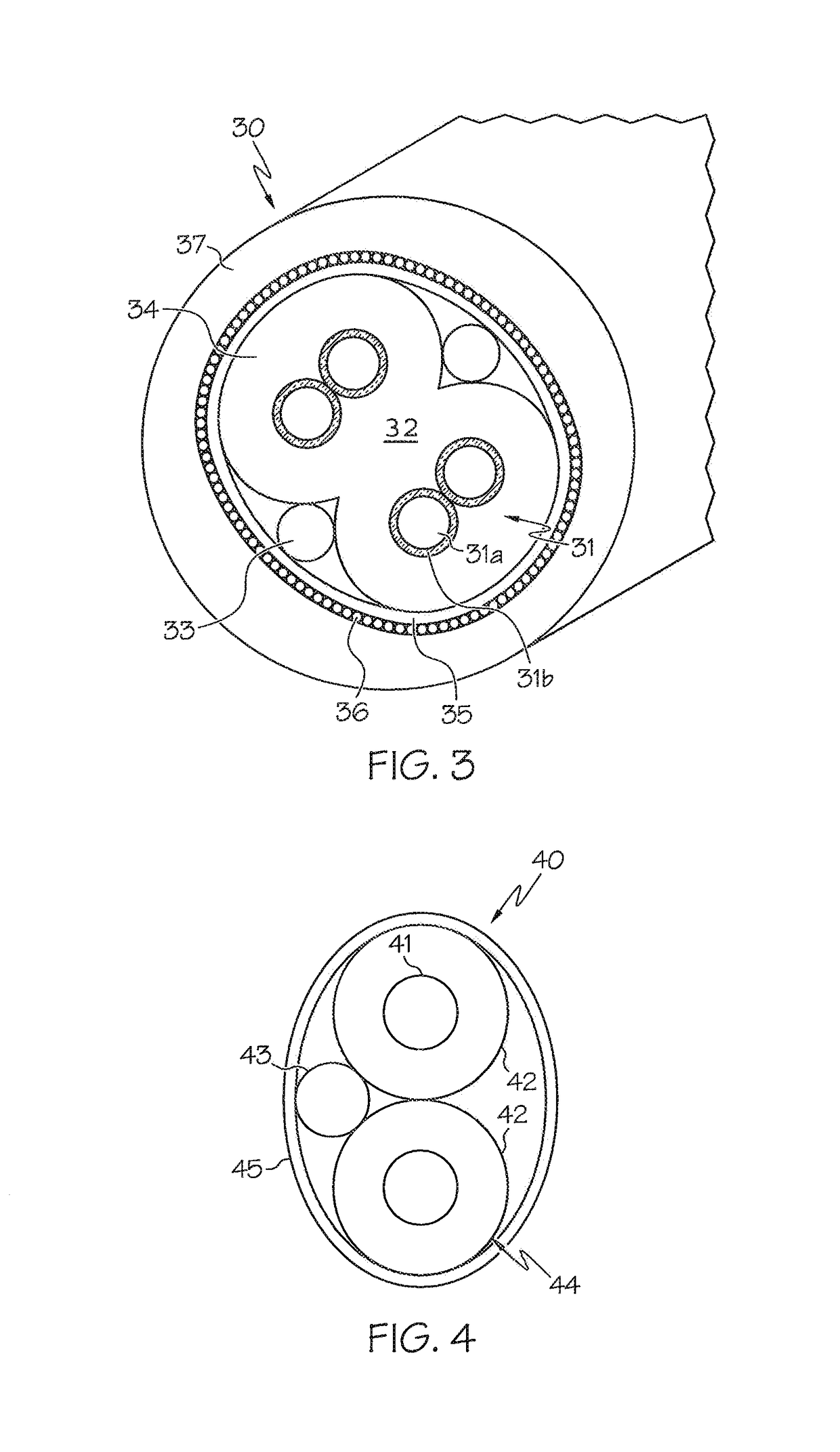
[0035]Transmission cables, built in accordance with the present invention, will now be described with initial reference to FIGS. 1-9. The conductor strands and wires in each of these descriptions are copper. In other embodiments, however, the conductor strands and wires may also consist of various grades and combinations of copper and silver.

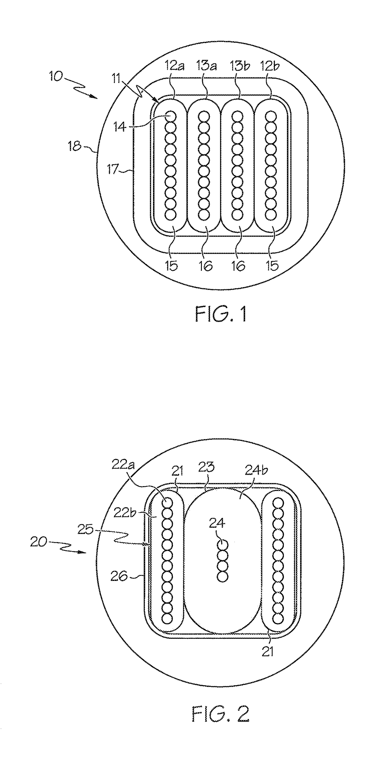
[0036]Referring now to FIG. 1, the design of an inventive four (4) conductor transmission cable 10 is defined by four substantially flat conductors each consisting of ten (10) solid metallic strands laid side by side in direct contact in a flat parallel configuration within an extruded insulator. The four conductors are stacked together to form a rectangular profile 11. These conductors include shield conductors embodied by a first outer conductor 12a and a second outer conductor 12b, and signal conductors embodied by a first inner conductor 13a and a second inner conductor 13b. The first outer conductor 12a and the second outer conductor 12b ea...


PUM

PropertyMeasurementUnit
diameteraaaaaaaaaa
diameteraaaaaaaaaa
thicknessaaaaaaaaaa

Abstract

A transmission line cable that utilizes a plurality of substantially flat insulated conductors, each consisting of two or more solid metallic strands laid side by side in a parallel configuration within an extruded insulator. The plurality of insulated conductors are stacked into groups of two or more and may be utilized as signal conductors or shield conductors. Once the insulated conductors are stacked, the stack is twisted together, and either wrapped in a conductive insulator, placed in an extruded non-conductive insulator, or both, creating a cable that is stable, flexible, and has improved transmission characteristics, including reduced attenuation, noise and signal skew.

Description

CROSS REFERENCE TO RELATED APPLICATIONS[0001]This application is a continuation in part and claims priority to non-provisional application Ser. No. 12 / 870,268, filed on Aug. 27, 2010, which claimed priority to provisional application No. 61 / 238,877, filed on Sep. 1, 2009.STATEMENT REGARDING FEDERALLY SPONSORED RESEARCH OR DEVELOPMENT[0002]N / ABACKGROUND OF THE INVENTION[0003]Field of the Invention[0004]The present invention relates to cables for transmitting electrical signals or power. The signals may be either analog or digital in nature. In particular, the present invention relates to extruded cables wherein the conductors consist of groups of round strands laid in parallel to form flat conductors with high flexibility and improved transmission characteristics, including reduced attenuation, noise and signal skew.[0005]Description of the Related Art[0006]The concept of increasing the mutual inductance of a cable to reduce its attenuation was originally disclosed in 1904 by Michael...

Claims


Application Information

Patent Timeline
Patent Type & Authority Patents(United States)
IPC IPC(8): H01B13/06H01B7/00H01B13/14H01B11/20H01B11/06
CPCH01B7/00H01B13/06H01B13/14H01B11/20H01B11/06H01B7/0823H01B7/0861H01B7/0892
Inventor SALZ, DAVID
Owner WIREWORLD BY DAVID SALZ
Why Eureka
Try Eureka