Thermal oscillator

a technology of thermal oscillator and thermal sensing device, which is applied in the direction of electrical apparatus, piezoelectric/electrostrictive/magnetostrictive devices, lighting and heating apparatus, etc., can solve the problem of induced radial heat flux from heat sources, and achieve the effect of enhancing the efficiency of converters based on pyroelectric, pyromagnetic or piezoelectric effects, and enhancing the sensitivity of thermal sensing devices

Active Publication Date: 2017-05-02
INT BUSINESS MASCH CORP
View PDF17 Cites 7 Cited by
  • Summary
  • Abstract
  • Description
  • Claims
  • Application Information

AI Technical Summary

Benefits of technology

[0017]The sandwich of the thermal switch between two thermal conductors may be advantageous for adjusting the temperature profile in the thermal oscillator.
[0039]Recapitulating the above three embodiments, the entire switching material, e.g. vanadium dioxide, of the thermal switch undergoes a phase transition in very short time intervals, e.g. picoseconds or nanoseconds, instead of gradually throughout the switching layer. Thus, it can be ensured that the thermal oscillator never finds a stationary state. So, the thermal oscillator swings between its two states for providing said oscillating heat flux. Thus, the switching material shows a single domain behavior during its phase transition leading to a step-like response in thermal conductance versus temperature dependence. For the example of vanadium dioxide as the material for the thermal switch, this happens if the layer of the thermal switch is thin, for example between 10 nm to 100 nm with a crystallographic c-axis orientation in parallel to the incident heat flux direction. Furthermore, the lateral dimension of the active switching layer of the thermal switch may be restricted to avoid the formation of a multi-phase system within the lateral direction of the film. By applying these geometrical restrictions, e.g. tuning area and thickness of the switching material, single-phase behavior of the phase change layer of the thermal switch can be ensured.
[0053]In an embodiment, the device is embodied as an energy harvesting device. Energy converters based on pyroelectric effects hold the promise to outperform existing thermal electric energy converters (see reference [1]) in terms of energy conversion efficiency. The present thermal oscillator may enhance said efficiency, because the conversion principle of such an energy converter is based on temporary changes in temperature which may be provided by said thermal oscillator. By means of said present thermal oscillator for creating temperature oscillations, the efficiency of converters based on pyroelectric, pyromagnetic or piezoelectric effects may be boosted.
[0054]In an embodiment, the device is embodied as a sensing device. The creation of an oscillating heat source as created by the present thermal oscillator may enhance the sensitivity of a thermal sensing device, e.g. in calorimetry. By means of the present thermal oscillator, the overhead of producing oscillating heat sources may be limited. Additionally, subsequent physical sensing mechanisms based on electrical, magnetic or optical effects may be influenced by thermal modulation provided by the present thermal oscillator in combination with lock-in techniques.

Problems solved by technology

The device layer and the sacrificial layers have relative high and low thermal conductivities, resulting in induced radial heat flux from the heat sources.

Method used


Image

  • Thermal oscillator
  • Thermal oscillator
  • Thermal oscillator

Examples


first embodiment

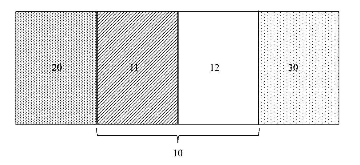
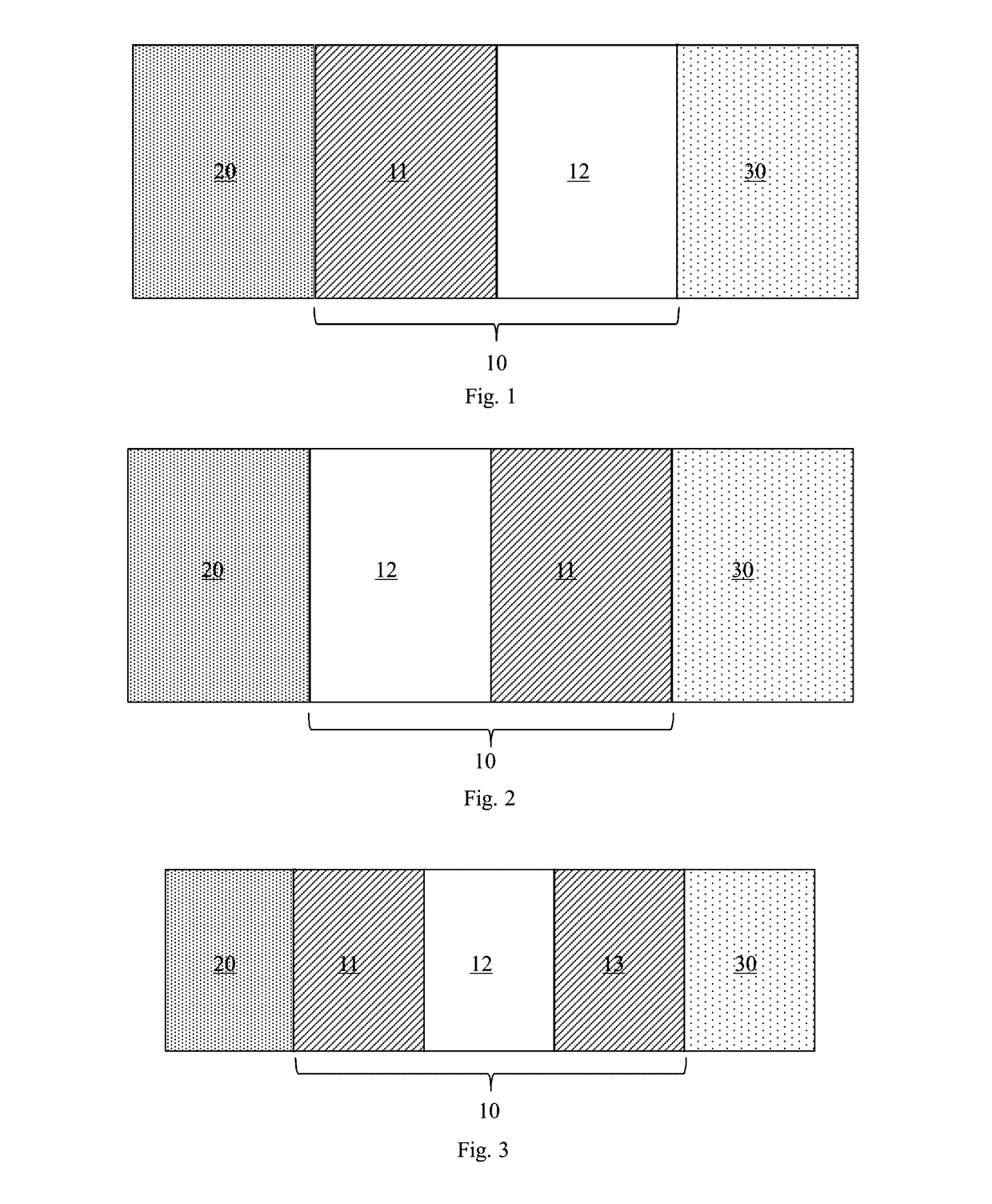
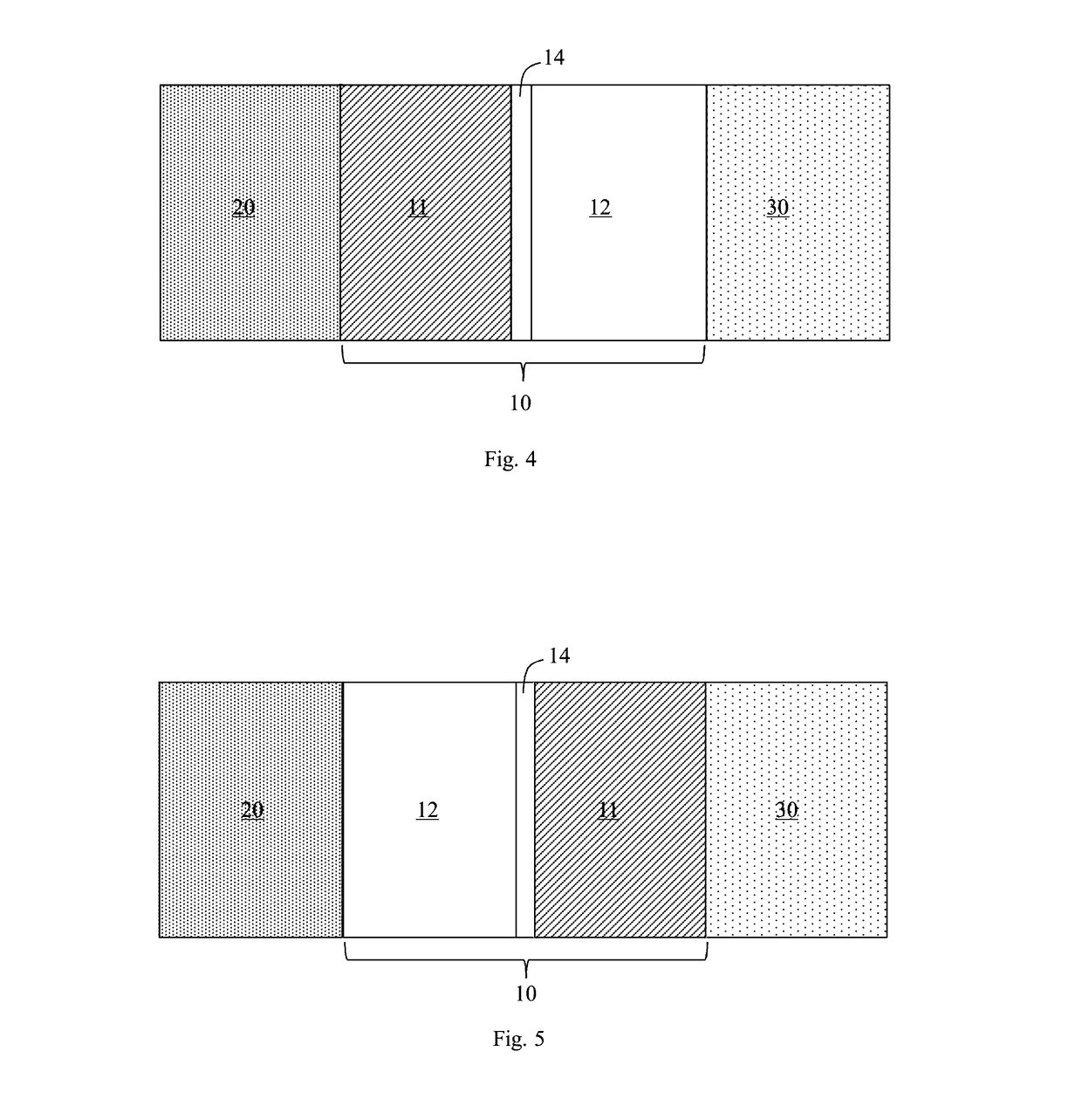
[0078]In FIG. 1, a schematic block diagram of a thermal oscillator 10 for creating an oscillating heat flux from a stationary spatial thermal gradient between a warm reservoir 20 and a cold reservoir 30 is depicted.

[0079]The thermal oscillator 10 comprises a thermal conductor 11 and a thermal switch 12. The thermal conductor 11 is configured to contact a heat flux from the warm reservoir 30 towards the cold reservoir 20.

[0080]The thermal switch 12 is coupled to the thermal conductor 11. In particular, the thermal switch 12 is connected to the thermal conductor 11. The thermal switch 12 is configured to receive the heat flux conducted by the thermal conductor 11. The thermal switch 12 has a certain difference between two states S1, S2 of thermal conductance, (see FIG. 8) for example due to metal-insulator phase transitions. In combination with the thermal conductor 11, alternating phase transitions are created leading to thermal relaxations such that the oscillating heat flux is crea...

third embodiment

[0087]FIG. 7 shows a schematic block diagram of a thermal oscillator 10 for creating an oscillating heat flux from a stationary spatial thermal ingredient between a warm reservoir 20 and a cold reservoir 30 and corresponding temperature profiles for the oscillator being in a stationary state slightly below and above the switching temperature interval H

[0088]The temperature T is shown as a function of position P along the thermal oscillator 10 for two possible stationary states. FIG. 7 shows that depending on the state S1 or S2 of the thermal switch 12 of the thermal oscillator 10, the temperature distribution T along the thermal oscillator 10 changes approaching the two “idle” steady states S1, S2, given by the relative thermal conductance values of the thermal switch 12 and the thermal conductors 11, 13.

[0089]In FIG. 8, the conductance k of the thermal switch 12 of FIG. 1 as a function of temperature T is depicted. The thermal switch 12 is configured to switch at a first switching ...

second embodiment

[0093]FIG. 9 shows the thermal conductance of a thermal switch 12 as a function of temperature as suitable for the thermal oscillator 10 of the

[0094]In FIG. 10, a schematic block diagram of a seventh embodiment of a thermal oscillator 10 for creating an oscillating heat flux is shown. Additionally to the third embodiment of FIG. 3, the seventh embodiment of the thermal oscillator 10 of FIG. 10 comprises a thermal electrode 15. The thermal electrode 15 may be attached to the thermal conductor 11 and / or to the thermal switch 12 such that the created oscillating heat flux is receivable at an external device. The thermal electrode 15 may include a metal sheet for gripping the created oscillating heat flux.

[0095]In this regard, FIG. 11 shows the oscillating temperature Tel at the thermal electrode 15 of the thermal oscillator 10 of FIG. 10 as a function of time t.

[0096]Furthermore, FIG. 12 shows the heat transfer coefficient htc between a thermal switch and a thermal conductor for the tw...


PUM


Abstract

A thermal oscillator (10) for creating an oscillating heat flux from a stationary spatial thermal gradient between a warm reservoir (20) and a cold reservoir (30) is provided. The thermal oscillator (10) includes a thermal conductor (11) which is connectable to the warm reservoir (20) or to the cold reservoir (30) and configured to conduct a heat flux from the warm reservoir (20) towards the cold reservoir (30), and a thermal switch (12) coupled to the thermal conductor (11) for receiving the heat flux and having a certain difference between two states (S1, S2) of thermal conductance for providing thermal relaxation oscillations such that the oscillating heat flux is created from the received heat flux.

Description

FIELD OF THE INVENTION[0001]The invention relates to a thermal oscillator and to a device including at least one thermal oscillator.BACKGROUND[0002]A conventional thermal oscillator is described in document U.S. Pat. No. 4,044,558 A.[0003]Document U.S. Pat. No. 7,920,032 B2 shows an oscillator device based on thermal diffusion. The oscillator is adapted for generating an oscillator signal. The oscillator device has at least a first heater, a temperature sensor, signal processing means, and a voltage controlled oscillator. An output of the temperature sensor is connected to an input of the signal processing means; an output of the signal processing means is connected to an input of the voltage controlled oscillator. An output of the voltage controlled oscillator in a first feedback-loop has a first connection to an input of the at least one first heater. The voltage controlled oscillator, in use, is capable of generating an oscillator signal, the oscillator signal being provided as h...

Claims


Application Information

Patent Timeline
Patent Type & Authority Patents(United States)
IPC IPC(8): H01L37/02F28F13/00H01L35/00H01L37/04H01L41/113H03L1/02
CPCH01L37/02F28F13/00H01L37/04H01L41/113H03L1/02C01P2006/32F28F2013/008H01L35/00H10N15/10H10N10/00H10N15/20H10N30/30H03B28/00
Inventor GOTSMANN, BERNDMENGES, FABIAN
Owner INT BUSINESS MASCH CORP
Why Eureka
Try Eureka