Supercharge Your Innovation With Domain-Expert AI Agents!

Wind turbine generator

a wind turbine generator and generator technology, applied in the direction of motors, engine control, dynamo-electric machines, etc., can solve the problems of reducing unbalanced attracting loads that generate pull force, and poor performance, so as to prolong the life of the generator and improve the performance. , the effect of more uniform air gap

Active Publication Date: 2017-05-02
GE RENEWABLE TECH WIND BV
View PDF21 Cites 0 Cited by
  • Summary
  • Abstract
  • Description
  • Claims
  • Application Information

AI Technical Summary

Benefits of technology

This patent describes a new design for a generator that has advantages, such as lasting longer and performing better. This is because the default design of the generator has a misshapen rotor and stator, which results in a better shape when the generator is under load. The new design can improve the performance of the generator without increasing its weight or mass.

Problems solved by technology

These deformations may cause degradation of the air gap between the rotor and the stator, said degradation producing bad performance and reduction of the life of the generator.
It is known, for example, that deformations of the rotor / stator and the consequent degradation of the air gap causes unbalanced attracting loads that generate a pull force.
This pull force, which increases as air gap degradation increases, may affect the generator's performance, the life of the generator's components such as rotor, stator, generator bearing, elastic coupling and others components of the wind turbine (e.g. frames).
However, the application of this approach generates very heavy structures whose e.g. manufacture and transport are very costly.
Nevertheless, the approaches commented in the two previous paragraphs usually involve complex geometries, introduce additional components, etc.
The resulting wind turbine generators may thus be expensive and difficult to maintain.

Method used


Image

  • Wind turbine generator
  • Wind turbine generator
  • Wind turbine generator

Examples


first embodiment

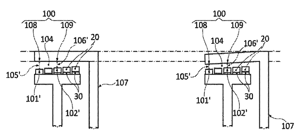
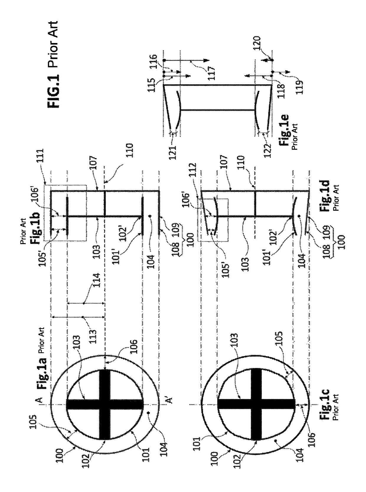
[0108]In relation to FIG. 3, FIGS. 3a and 3b show a prior art rotor-stator configuration, and FIGS. 3c and 3d show a rotor-stator configuration according to the invention. FIG. 3a refers to a section of a rotor-stator configuration very similar to the section 111 of FIG. 1b, with the only difference that the gap-delimiting region 101′,102′ of the rotor is constituted by permanent magnets 20. The most relevant aspect of 3a is that it represents the substantial uniformity of the air gap 104 in the default situation along the entire air gap 104 (in this particular view). In this respect, 3a reflects that the width 106′ of the air gap 104 in zones 109 closer to the supporting element 107 and the width 105′ of the air gap 104 in zones 108 more distant from the supporting element 107 are substantially the same.

[0109]FIG. 3b shows the configuration of FIG. 3a deformed under the effect of operational loads. For reasons of simplicity, the rotor is assumed as not deformed because e.g. the rot...

third embodiment

[0119]FIG. 5 is a schematic representation of the prior art rotor-stator configuration shown in FIG. 3 (FIGS. 5a and 5b are identical to FIGS. 3a and 3b respectively) and a particular rotor-stator configuration according to the invention. FIG. 5c shows said particular rotor-stator configuration in accordance with the anticipated deformations (shown in 5b) of the prior art rotor-stator configuration 5a due to operational loads. Particularly, 5c shows how the surface of the rotor on which the magnets 20 are fixed is selectively machined 50,51 with the objective of obtaining the uniform air gap 104 of 5d when operational loads are present.

[0120]Said selective machining 50,51 of 5c has the goal of moving the gap-delimiting region 101′,102′ of the rotor away from the gap-delimiting region 100 of the stator, in such a way that the width of the air gap 104 increases as the distance from the supporting element 107 of the stator increases. For example, 5c shows that the width 105′ of the air...

fourth embodiment

[0125]FIG. 6 is a schematic representation of the prior art rotor-stator configuration shown in FIG. 3 (FIGS. 6a and 6b are identical to FIGS. 3a and 3b respectively) and a particular rotor-stator configuration according to the invention. In this case, 6a and 6b additionally show the rotational axis 60 of the rotor and the axis of symmetry 61 of the stator, said two axes 60,61 being the same axis because the rotor-stator configuration of 6a and 6b is a coaxial configuration. FIG. 6c shows the particular rotor-stator configuration in accordance with the anticipated deformations (shown in 6b) of the prior art rotor-stator configuration 6a due to operational loads. Particularly, 6c shows how the rotational axis 60 is inclined with respect to the axis of symmetry 61 of the stator with the objective of obtaining the uniform air gap 104 of 6d when operational loads are present.

[0126]The inclination of the rotational axis 60 with respect to the axis of symmetry 61 of the stator has the goa...


PUM


Abstract

A wind turbine generator comprising a rotor, a stator and an air gap between a gap-delimiting region of the stator and a gap-delimiting region of the rotor; wherein the rotor and / or the stator are deformable under operational loads and configured in such a way that the air gap resulting from the presence of operational loads is more uniform than the air gap in the absence of operational loads. A method for optimizing an air gap between a gap-delimiting region of a stator and a gap-delimiting region of a rotor of a wind turbine generator, said rotor and / or said stator being deformable under operational loads and said optimization consisting in that the air gap resulting from the presence of the set of operational loads is more uniform than the air gap in the absence of the set of operational loads.

Description

[0001]This application claims the benefit of European Patent Application EP11382246 filed 18 Jul. 2011 and U.S. Provisional Patent Application Ser. No. 61 / 536,291 filed 19 Sep. 2011.[0002]The present invention relates to a wind turbine generator comprising a rotor, a stator and an air gap between a gap-delimiting region of the stator and a gap-delimiting region of the rotor, said rotor and / or stator being deformable under operational loads.[0003]The present invention also relates to a method for optimizing an air gap between a gap-delimiting region of a stator and a gap-delimiting region of a rotor of a wind turbine generator, said rotor and / or said stator being deformable under operational loads.BACKGROUND ART[0004]Wind turbine generators (e.g. self-excited or with permanent magnets) may be exposed to deformations of their rotor and / or stator due to the effect of operational loads (e.g. weight of the rotor / stator, electromagnetic forces between the rotor and stator, etc.). These de...

Claims


Application Information

Patent Timeline
Patent Type & Authority Patents(United States)
IPC IPC(8): H02K7/18G06F17/50H02K15/16H02K1/06F03D9/00F03D17/00F03D7/02
CPCH02K7/183F03D7/0272F03D9/25F03D17/00G06F17/5009H02K1/06H02K7/1838H02K15/16F05B2220/7066F05B2270/305H02K2201/03Y02E10/723Y02E10/725Y02E10/72G06F30/20
Inventor FABREGAT BALBOA, GUILLERMOGARCIA I ERILL, DANIELCLARAMUNT ESTECHA, SANTIAGO
Owner GE RENEWABLE TECH WIND BV
Features
  • R&D
  • Intellectual Property
  • Life Sciences
  • Materials
  • Tech Scout
  • Unparalleled Data Quality
  • Higher Quality Content
  • 60% Fewer Hallucinations
Learn More