
TFT array substrate structure

a thin film transistor and array substrate technology, applied in the field of display technology, can solve the problems of small capacitance that does not suit the needs of high-quality display panels, and achieve the effects of enhancing display panel performance, increasing storage capacitor capacity, and increasing storage capacitor capacity

Active Publication Date: 2017-05-09
WUHAN CHINA STAR OPTOELECTRONICS TECH CO LTD
View PDF18 Cites 12 Cited by
  • Summary
  • Abstract
  • Description
  • Claims
  • Application Information

AI Technical Summary

Benefits of technology

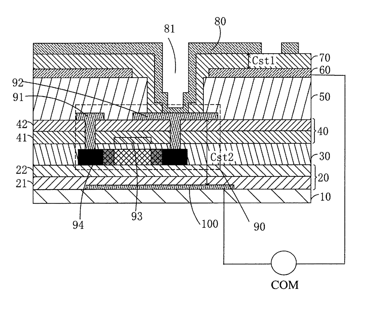
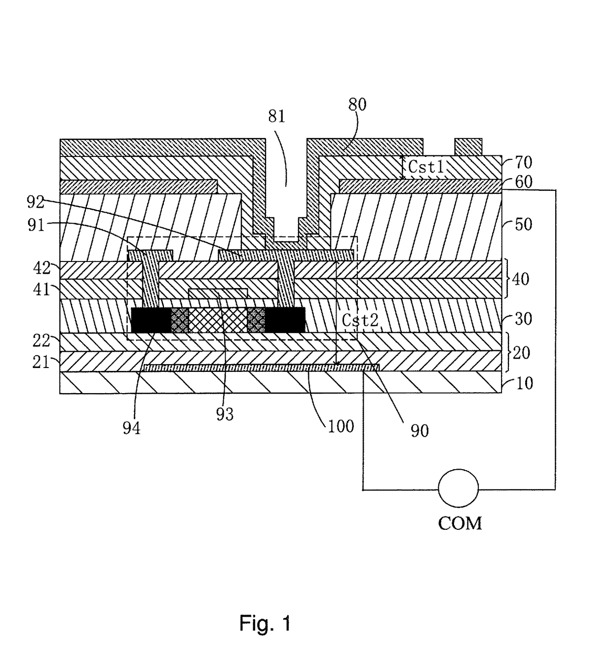
The present invention provides a thin-film transistor (TFT) array substrate structure that increases the capacity of the storage capacitor, improves the performance of a display, and enhances product competition power without reducing the aperture ratio. This is achieved through a metal light-shielding layer that forms two storage capacitors in parallel with the TFTs, which increases the storage capacity without affecting the aperture ratio. The metal light-shielding layer is positioned to correspond to an area where light needs to be shielded, making the modification to the layer without affecting the aperture ratio.

Problems solved by technology

Such a storage capacitor has a relatively small capacitance that does not suit the needs of high quality display panels.

Method used


Image

  • TFT array substrate structure
  • TFT array substrate structure
  • TFT array substrate structure

Examples


Embodiment Construction

[0030]To further expound the technical solution adopted in the present invention and the advantages thereof, a detailed description is given to a preferred embodiment of the present invention with reference to the attached drawings.

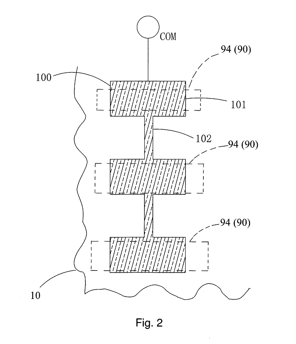
[0031]Referring to both FIGS. 1 and 2, the present invention provides a thin-film transistor (TFT) array substrate structure, which comprises: a backing plate 10, a patterned metal light-shielding layer 100 formed on the backing plate 10, a first insulation layer 20 covering on the patterned metal light-shielding layer 100, a plurality of TFTs 90 formed on the first insulation layer 20 and arranged in the form of an array, a planarization layer 50 covering on the TFTs 90, a common electrode 60 formed on the planarization layer 50, a protection layer 70 covering on the common electrode 60, and a patterned pixel electrode 80 formed on the protection layer 70.

[0032]Each of the TFTs 90 comprises: a semiconductor layer 94 formed on the first insulation layer 2...


PUM

PropertyMeasurementUnit
voltageaaaaaaaaaa
electric fieldaaaaaaaaaa
coupling capacitanceaaaaaaaaaa

Abstract

A TFT array substrate structure includes a patterned metal light-shielding layer that includes a plurality of metal light-shielding blocks arranged in an array and a narrowed metal strip connected between two adjacent ones of the metal light-shielding blocks. The metal light-shielding layer and a common electrode are connected to and receive a common voltage signal. For each of TFT, the pixel electrode is connected to a drain electrode of the TFT; the pixel electrode has a portion overlapping the common electrode to form a first storage capacitor; and the metal light-shielding layer has a portion overlapping the drain electrode and the pixel electrode to form a second storage capacitor. The first storage capacitor and the second storage capacitor are connected in parallel to increase the capacity of the storage capacitor. The metal light-shielding layer is arranged in a light-shielded area and thus the modification thereof does not affect aperture ratio.

Description

BACKGROUND OF THE INVENTION[0001]1. Field of the Invention[0002]The present invention relates to the field of display technology, and in particular to a thin-film transistor (TFT) array substrate structure.[0003]2. The Related Arts[0004]Liquid crystal displays (LCDs) have a variety of advantages, such as thin device body, low power consumption, and being free of radiation, and thus have wide applications, such as liquid crystal televisions, mobile phones, personal digital assistants (PDAs), digital cameras, computer monitors, and notebook computer screens, making them take a leading position in the field of flat panel displays.[0005]Most of the LCDs that are currently available in the market are backlighting LCDs, which comprise a liquid crystal display panel and a backlight module. The working principle of the liquid crystal display panel is that liquid crystal molecules are filled between a thin-film transistor (TFT) array substrate and a color filter (CF) substrate and a drive vo...

Claims


Application Information

Patent Timeline
Patent Type & Authority Patents(United States)
IPC IPC(8): H01L27/12G02F1/1362
CPCH01L27/1248H01L27/1222H01L27/1255G02F1/136209G02F1/136213H01L23/552G02F1/134372H01L27/124H01L29/78633
Inventor ZHAO, YUZHANG, ZHANDONG
Owner WUHAN CHINA STAR OPTOELECTRONICS TECH CO LTD
Learn More