Hip replacement navigation system and method

a navigation system and hip technology, applied in the field of hip replacement, can solve the problems of dislocation of the hip, unacceptably high percentage of patients with the relative high incidence of poor placement of the cup and ball components of the prosthetic hip joint, so as to improve the accuracy of the orientation of the componen

Active Publication Date: 2017-05-16
ORTHALIGN
View PDF499 Cites 53 Cited by
  • Summary
  • Abstract
  • Description
  • Claims
  • Application Information

AI Technical Summary

Benefits of technology

[0021]In some variations of the methods discussed herein, patient data can be used to enhance the accuracy of orientation of a component, such as the plane of the acetabulum. Patient data can include CT, MRI, X-Ray or other pre-operative planning data.

Problems solved by technology

One persistent issue with hip replacement is the relatively high incidence of poor placement of the cup and ball components of the prosthetic hip joint.
For several reasons an unacceptably high percentage of patients have the cup of the artificial hip joint out of alignment with this plane.
Unfortunately, misalignment can lead to dislocation of the hip as soon as within one year of the implantation procedure.
This is particularly problematic because recovery from a hip procedure can take many months.
Patients undergoing a revision so soon after the initial implantation will certainly be dissatisfied with their care, being subject to addition redundant surgery.
Of course, all surgery carries some degree of risk.
These poor outcomes are unsatisfactory for patients and surgeons and are inefficient for the healthcare system as a whole.
This is one of the key reasons why hip navigation has failed to be adopted by most of the market.
Additionally, altered leg length is a common patient complaint arising from hip replacement surgery and has been a common cause of medical malpractice lawsuits that arise from hip replacement.

Method used


Image

  • Hip replacement navigation system and method
  • Hip replacement navigation system and method
  • Hip replacement navigation system and method

Examples


Embodiment Construction

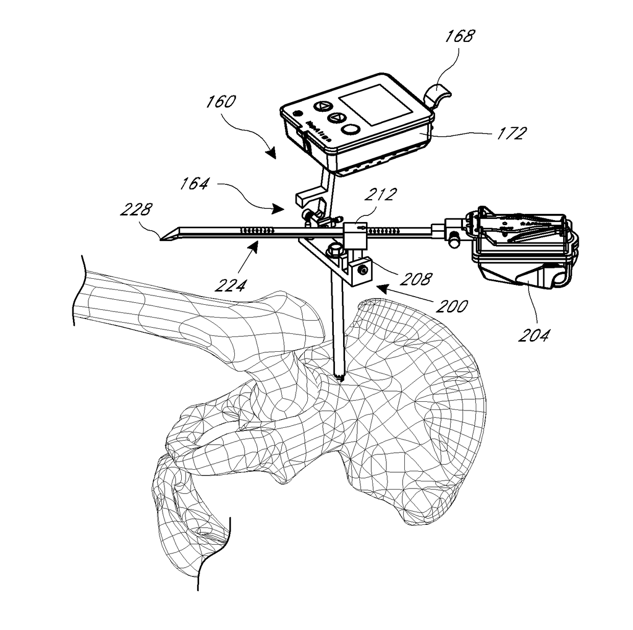
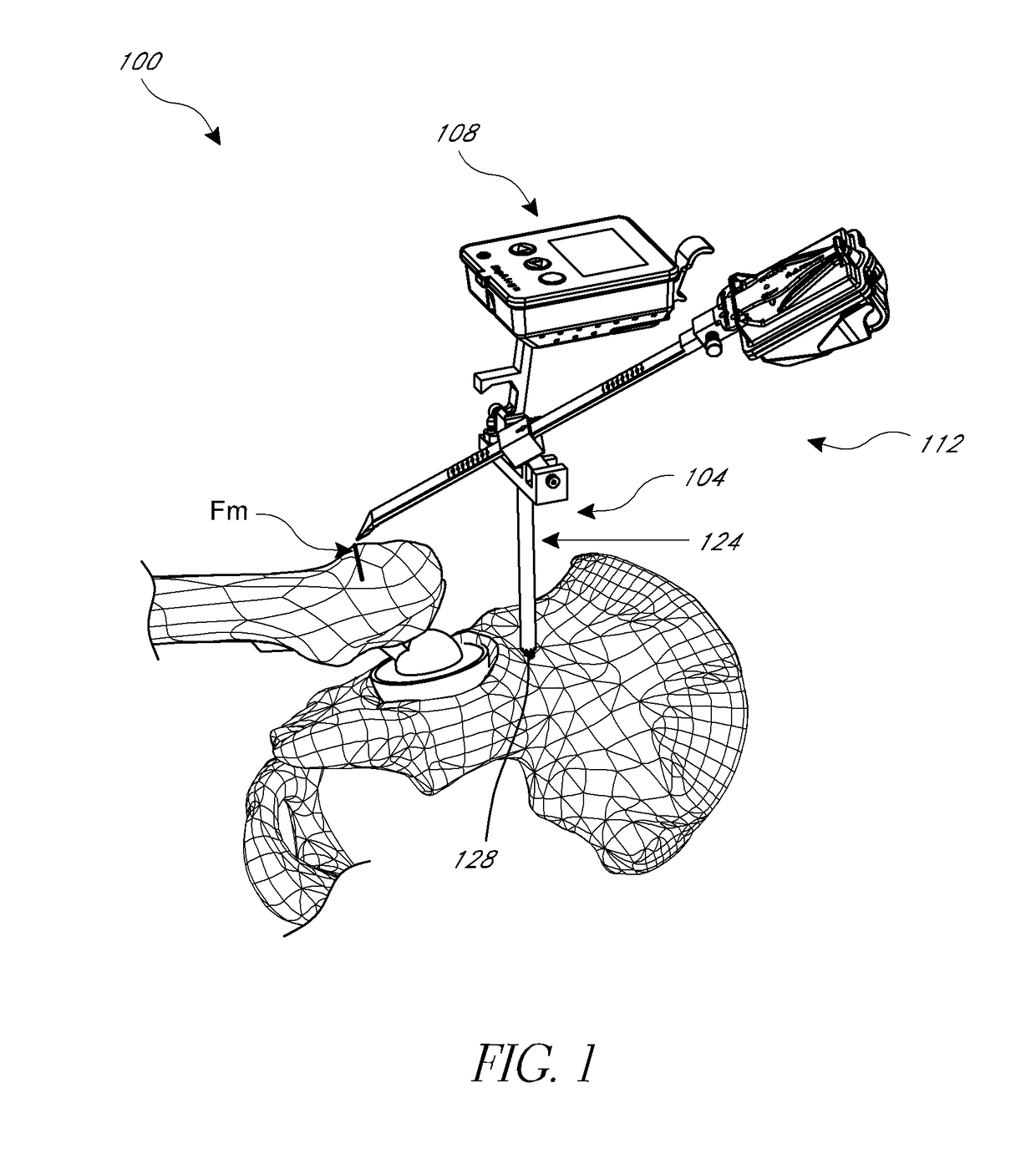
[0055]A variety of systems and methods are discussed below that can be used to improve outcomes for patients by increasing the likelihood of proper placement of a hip joint. These systems can be focused on inertial navigation techniques, close range optical navigation, or a combination of inertial and optical navigation.

I. Hip Navigation Using Inertial Sensors

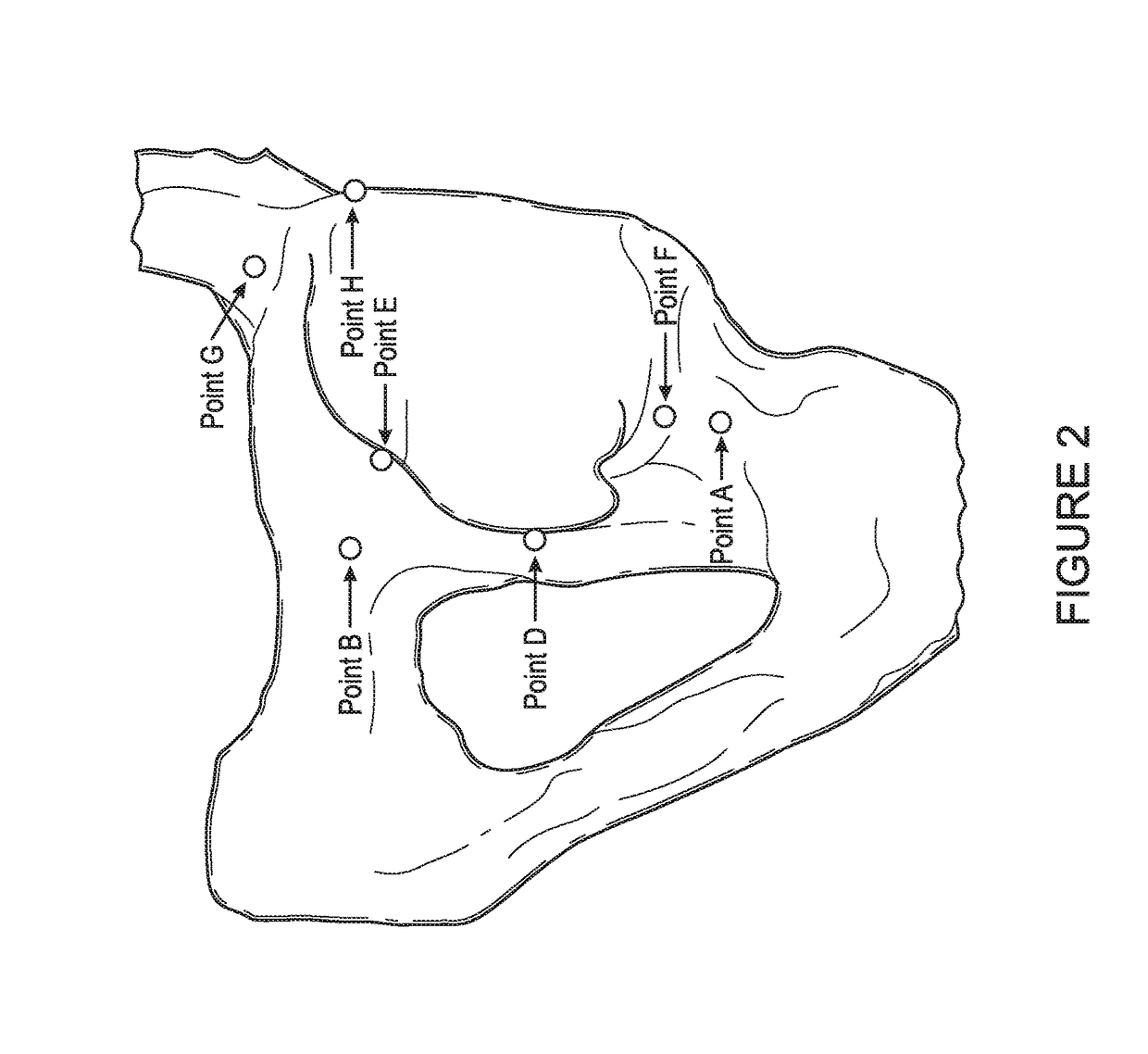
[0056]Systems and methods described below can improve prosthetic hip joint placement using navigation in connection with referencing anatomical landmarks, incorporating preoperative custom fit jigs based on imaging, and a combination of pre-operative imaging and landmark referencing. These hip procedures generally guide a prosthetic hip to an orientation within the acetabulum that minimizes the chance of dislocation due to impingement of the femoral neck on the cup or on bones around the acetabulum or other reasons related to suboptimal orientation of the prosthetic. Various techniques leverage population averages of proper pla...


PUM


Abstract

In another embodiment, a hip joint navigation jig is provided that includes an anatomical interface comprising a bone engagement portion. A registration jig is also provided that is coupled, e.g., removeably, with the anatomical interface. A rotatable member is provided for rotation about an axis that is not vertical when the jig is mounted to the bone adjacent to a hip joint and the registration jig is coupled with the anatomical interface. An anatomy engaging probe is coupled with the rotatable member for rotation about the axis and is translatable to enable the probe to be brought into contact with a plurality of anatomical landmarks during a procedure. An inertial sensor is coupled with the probe to indicate orientation related to the landmarks, the sensor being disposed in a different orientation relative to horizontal when the probe is in contact with the landmarks.

Description

INCORPORATION BY REFERENCE TO ANY PRIORITY APPLICATIONS[0001]Any and all applications for which a foreign or domestic priority claim is identified in the Application Data Sheet as filed with the present application including U.S. provisional application No. 61 / 683,167, filed Aug. 14, 2012, and U.S. provisional application No. 61 / 761,617, filed Feb. 6, 2013, are hereby incorporated by reference under 37 CFR 1.57.BACKGROUND OF THE INVENTION[0002]Field of the Invention[0003]This application is directed to the field of hip replacement, and particularly to surgical tools and methods for guiding the preparation of the bones in connection therewith.[0004]Description of the Related Art[0005]Hip replacement surgery is common and getting more common by the year. One persistent issue with hip replacement is the relatively high incidence of poor placement of the cup and ball components of the prosthetic hip joint. For example, the cup is optimally placed in a specific alignment with a plane inc...

Claims


Application Information

Patent Timeline
Patent Type & Authority Patents(United States)
IPC IPC(8): A61B17/17A61F2/46A61B90/10A61B34/20A61F2/34A61F2/30
CPCA61B34/20A61B17/1746A61B90/10A61F2/4609A61F2/4657A61B2034/2048A61B2034/2068A61F2/30942A61F2/34A61F2002/4687
Inventor VAN DER WALT, NICHOLASRYAN, MATTHEWNIELSEN, JONATHAN
Owner ORTHALIGN
Why Eureka
Try Eureka