Substrate material of iron-nickel alloy metal foil for CIGS solar cells

a technology of iron-nickel alloy metal foil and substrate material, which is applied in the direction of sustainable manufacturing/processing, final product manufacturing, electrolysis processes, etc., can solve the problems of increasing the width of the metal substrate material being processed, difficult to handle, and interlayer separation, and achieves the effect of simple process system

Active Publication Date: 2017-05-16
KOREA INST OF IND TECH
View PDF50 Cites 0 Cited by
  • Summary
  • Abstract
  • Description
  • Claims
  • Application Information

AI Technical Summary

Benefits of technology

[0016]The Fe—Ni alloy metal foil substrate material produced according to the present invention has a thermal expansion coefficient similar to that of CIS or CIGS. Thus, when it is used as a substrate for a solar cell, a solar cell fabrication process does not require a special process design, and even after fabrication of the solar cell, interlayer separation caused by thermal expansion in the solar cells does not occur.
[0017]In addition, the present invention employs an electroforming technique that utilizes a simple process system, unlike a rolling process. Thus, the present invention makes it possible to produce a metal foil substrate material that is wide, thin and flexible.

Problems solved by technology

Glass substrates are transparent and are flexible when processed to have a thin thickness, but are difficult to handle.
Meanwhile, in the case in which a solar cell is to be fabricated on a stainless steel foil (thin stainless substrate material) or plastic substrate, when heat is applied to the substrate during vapor deposition or in the thin-film cell layer formation and selenization processes, there may be a problem in that interlayer separation occurs, because the substrate and the CIGS layer have different thermal expansion coefficients.
This technology has limitations in increasing the width of the metal substrate material being processed, and thus is disadvantageous for producing a large-area substrate using a large-area production process with reduced production costs.
In addition, it is generally difficult for this technology to obtain a substrate material having a thickness of 0.1 mm or less.

Method used


Image

  • Substrate material of iron-nickel alloy metal foil for CIGS solar cells
  • Substrate material of iron-nickel alloy metal foil for CIGS solar cells
  • Substrate material of iron-nickel alloy metal foil for CIGS solar cells

Examples


example 1

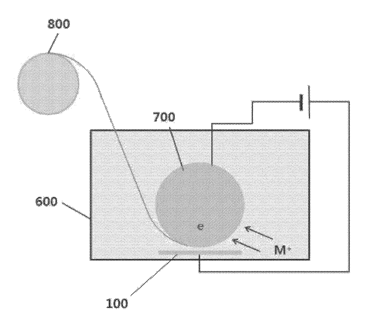
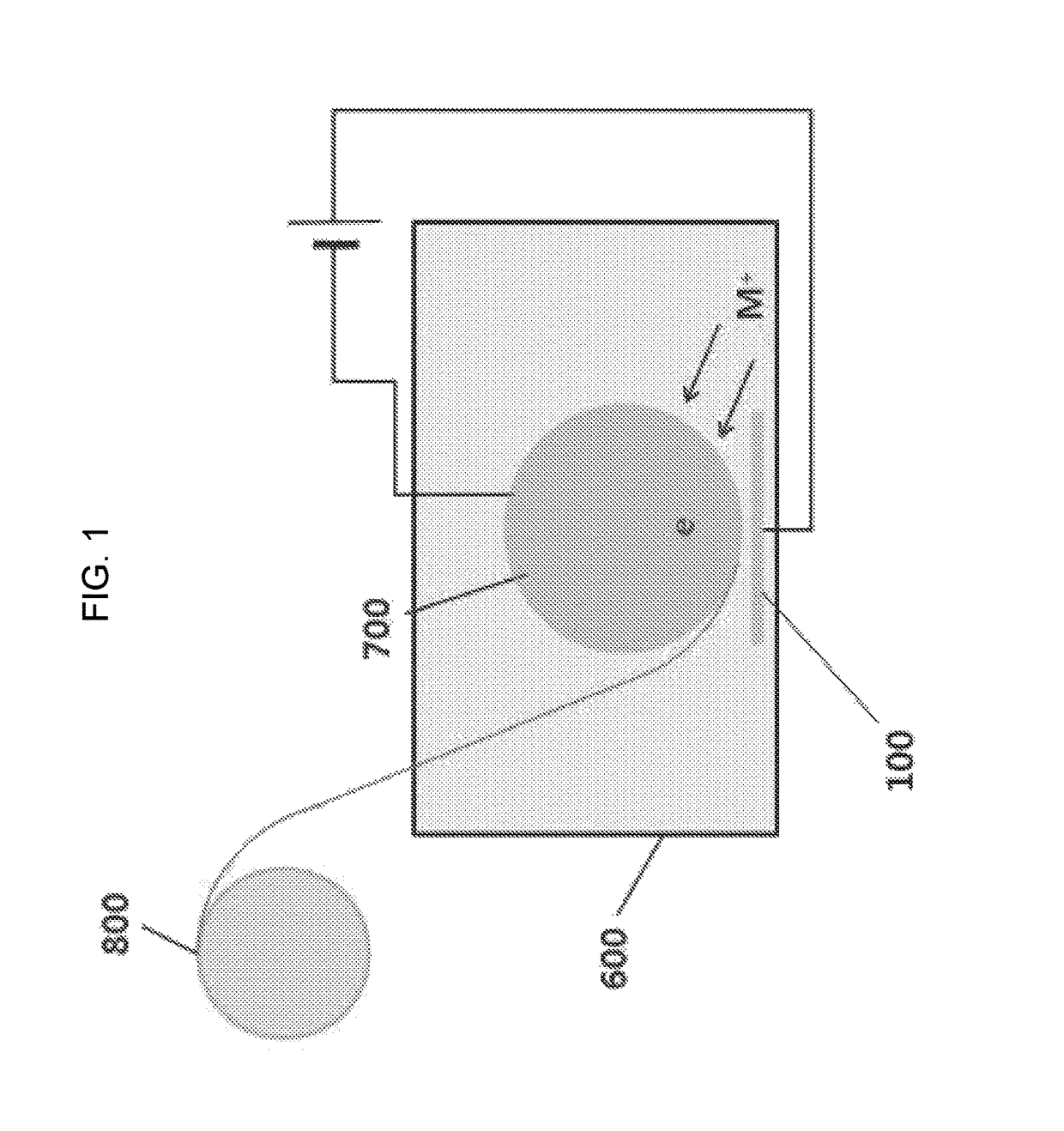
[0042]An alloy metal foil substrate material composed of Fe-46 wt % Ni was produced using an electrolyte solution having the following composition and the electroforming apparatus shown in FIG. 1. Specifically, the electrolyte solution contained 200 g / L of nickel sulfamate, 20 g / L of iron (II) chloride 4-hydrate, 20 g / L of boronic acid, 0.5 g / L of sodium lauryl sulfate, 2 g / L of saccharin and 1 g / L of an antioxidant (ascorbic acid) and had a pH of 3.0. The electrolyte solution was maintained at a temperature of 60° C. and controlled to a current density of 56 mA / cm2, thereby producing a metal foil substrate material composed of Fe-46 wt % Ni and having a thickness of 30 μm. The produced substrate material had a grain size of 15-20 μm. When the produced substrate material was subjected to a structure stabilization process under a hydrogen atmosphere at a temperature of 400˜1000° C. for 1 hour, the grain size increased to 0.1-10 μm.

[0043]In the cases in which (a) the produced Fe—Ni su...

example 2

[0044]An alloy metal foil substrate material composed of Fe-48 wt % Ni was produced in a manner similar to that described in Example 1 using an electrolyte solution having a composition controlled to provide Fe-48 wt % Ni.

[0045]In the cases in which (a) the produced Fe—Ni substrate material was not subjected to a structure stabilization process (heat treatment), (b) it was heat-treated under a hydrogen atmosphere at 400° C. for 1 hour, (c) it was heat-treated under a hydrogen atmosphere at 500° C. for 1 hour, and (d) it was heat-treated under a hydrogen atmosphere at 600° C. for 1 hour, the thermal expansion coefficient of the Fe—Ni metal, foil substrate material as a function of the temperature of the structure stabilization process was measured by thermo-mechanical analysis (TMA), and the results of the measurement are shown in FIG. 4. As can be seen in FIG. 4, when the structure stabilization process was performed at 600° C., the average of CTEs in the temperature range (20° C. t...

example 3

[0046]An alloy metal foil substrate material composed of Fe-50 wt % Ni was produced in a manner similar to that described in Example 1 using an electrolyte solution having a composition controlled to provide Fe-50 wt % Ni.

[0047]In the cases in which (a) the produced Fe—Ni substrate material was not subjected to a structure stabilization process (heat treatment), (b) it was heat-treated under a hydrogen atmosphere at 400° C. for 1 hour, (c) it was heat-treated under a hydrogen atmosphere at 500° C. for 1 hour, and (d) it was heat-treated under a hydrogen atmosphere at 600° C. for 1 hour, the thermal expansion coefficient of the Fe—Ni metal foil substrate material as a function of the temperature of the structure stabilization process was measured by thermo-mechanical analysis (TMA), and the results of the measurement are shown in FIG. 5. As can be seen in FIG. 5, when the structure stabilization process was performed at 600° C., the average of CTEs in the temperature range (20 to 500...


PUM

PropertyMeasurementUnit
temperatureaaaaaaaaaa
thicknessaaaaaaaaaa

Abstract

The present invention relates to an exclusive alloy substrate material for CIGS solar cells. Particularly, the present invention provides a substrate material having a thermal expansion coefficient similar to that of a CIGS layer. The substrate material according to the present invention may prevent damage such as interlayer separation due to differing thermal expansion coefficients from occurring because the substrate material has a thermal expansion coefficient similar to that of the CIGS layer.

Description

[0001]This application is the U.S. national phase of International Application No. PCT / KR2011 / 010222, filed 28 Dec. 2011, which designated the U.S. and claims priority to KR Application No. 10-2011-0119595, filed 16 Nov. 2011, the entire contents of each of which are hereby incorporated by reference.TECHNICAL FIELD[0002]The present invention relates to an alloy metal foil substrate material for a Cu—In—Se (CIS) or Cu—In—Ga—Se (CIGS) solar cell, and more particularly to a substrate material which can be used as a substrate material for a flexible CIGS solar cell and is made of an Fe—Ni alloy foil while having a thermal expansion behavior similar to that of a CIGS compound semiconductor.BACKGROUND ART[0003]A CIS solar cell and a CIGS solar cell are thin film solar cells that comprise three elements (Cu, In and Se) and four elements (Cu, In, Ga and Se), respectively. The CIGS solar cells have higher photoelectric conversion efficiency than Si thin-film solar cells, and the related mark...

Claims


Application Information

Patent Timeline
Patent Type & Authority Patents(United States)
IPC IPC(8): C22C38/08C25D1/04C22C30/00H01L31/032H01L31/0352H01L31/0392C21D1/04C22C19/03
CPCC22C38/08C25D1/04H01L31/0322H01L31/03928H01L31/0352C22C19/03C22C30/00Y02E10/541Y02P70/521Y02P70/50H01L31/0445
Inventor YIM, TAI HONGLEE, HEUNG YEOLHWANG, TAE JINSONG, YOUNG SIKCHO, YONG KILEE, MIN SUHAN, YOON HO
Owner KOREA INST OF IND TECH
Why Eureka
Try Eureka