
Wind turbine tower having a damper

a technology of wind turbine tower and damper, which is applied in the direction of motors, engine fuctions, building components, etc., can solve the problems of affecting the environment, and achieve the effect of convenient handling, less hazardous handling, and convenient handling

Active Publication Date: 2017-05-23
VESTAS WIND SYST AS
View PDF23 Cites 16 Cited by
  • Summary
  • Abstract
  • Description
  • Claims
  • Application Information

AI Technical Summary

Benefits of technology

The patent describes a wind turbine tower damper that is designed to save mass and dampen oscillations in a more efficient way. The damper is made of disc-shaped elements that can be easily handled and moved into the nacelle by crane. The dampener can be adjusted by adding or removing elements, and it also includes a cylindrical container filled with damping elements or internal friction between the damper elements. The damper is supported by roller ball wheels that allow it to move in any horizontal direction with low friction, which makes it faster and more effective in dampening minor tower oscillations. Overall, the invention improves the performance and safety of wind turbine towers.

Problems solved by technology

Also, any accidental spilling of liquid is avoid, which could be detrimental to the environment.

Method used


Image

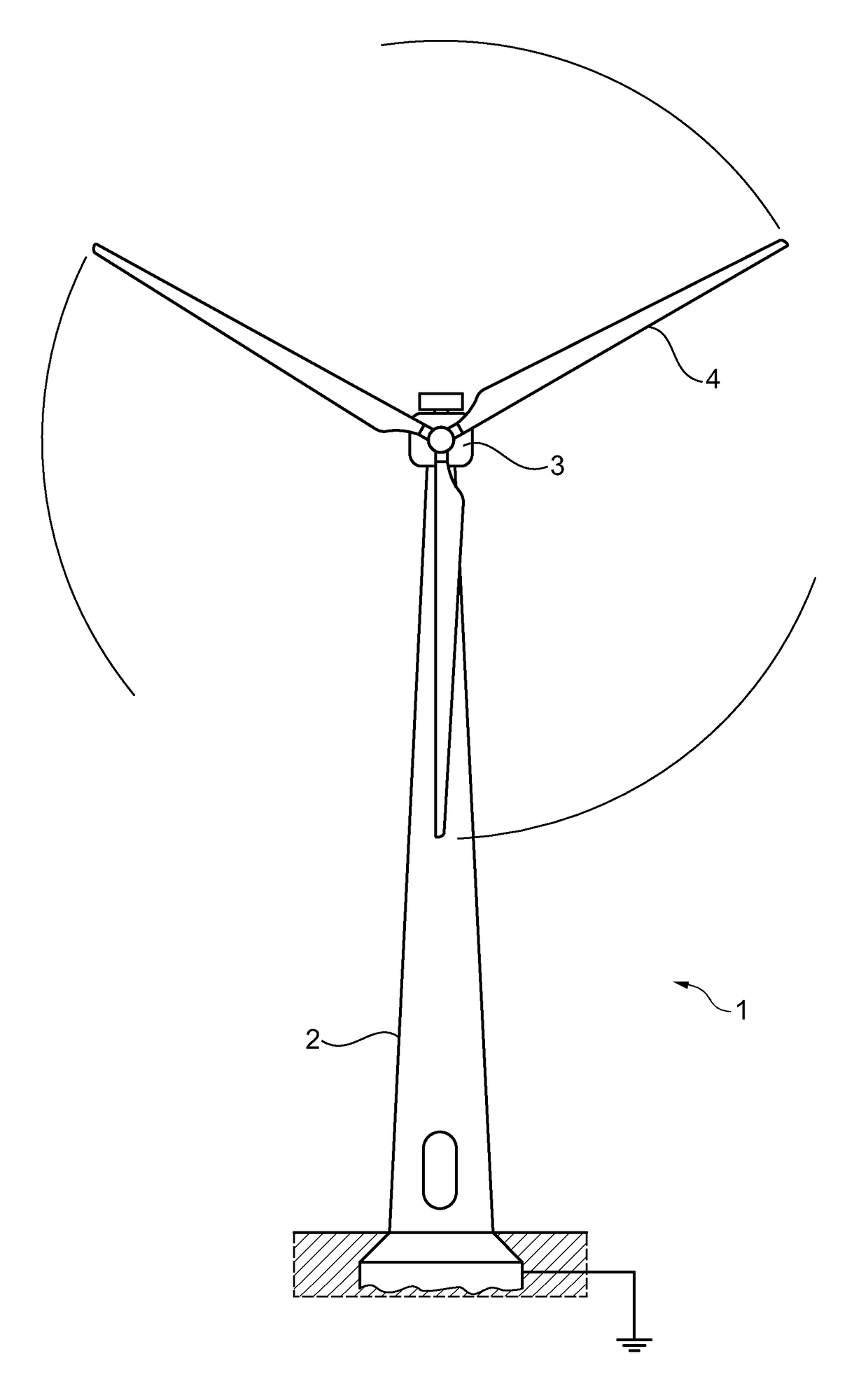
  • Wind turbine tower having a damper
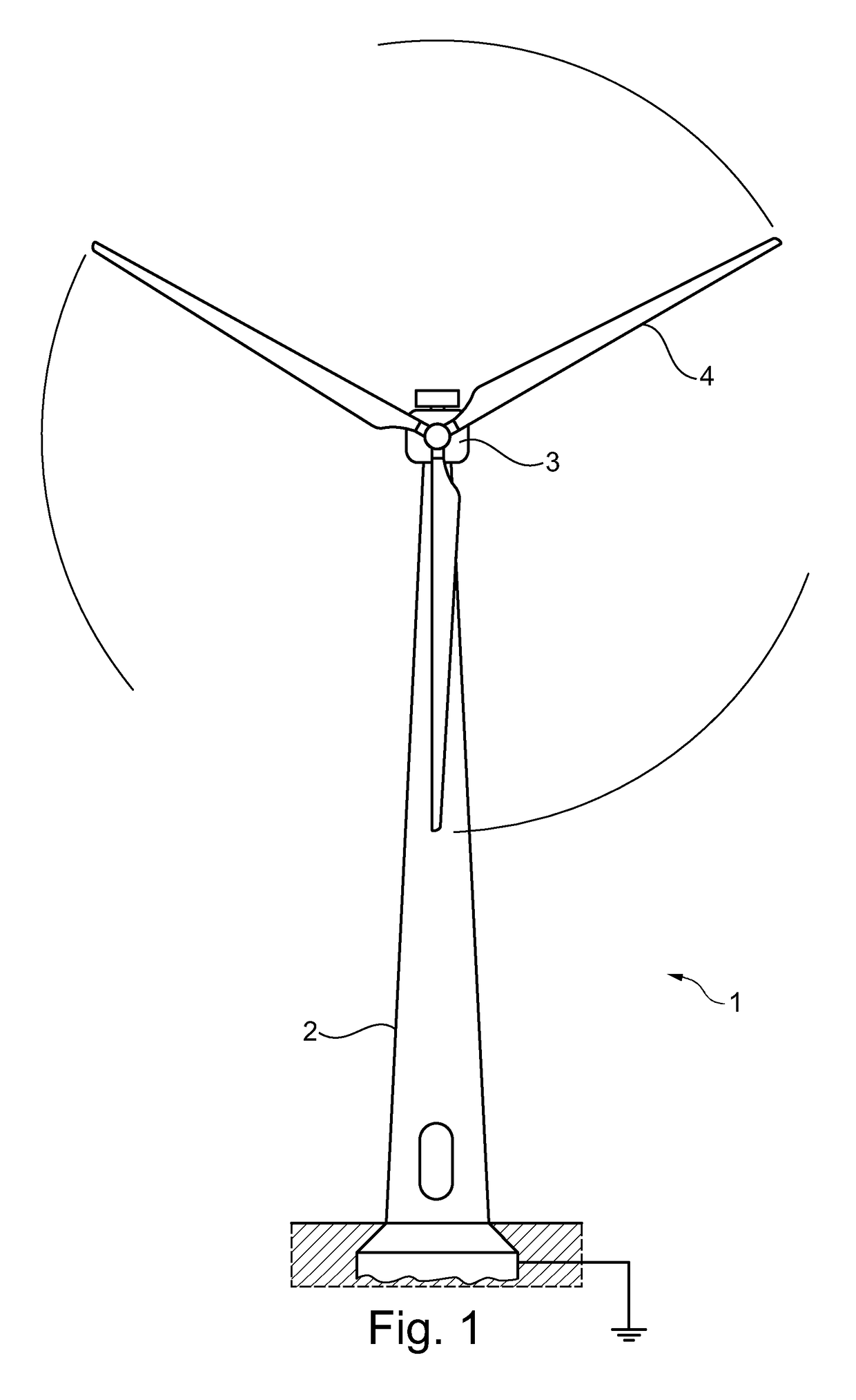
  • Wind turbine tower having a damper
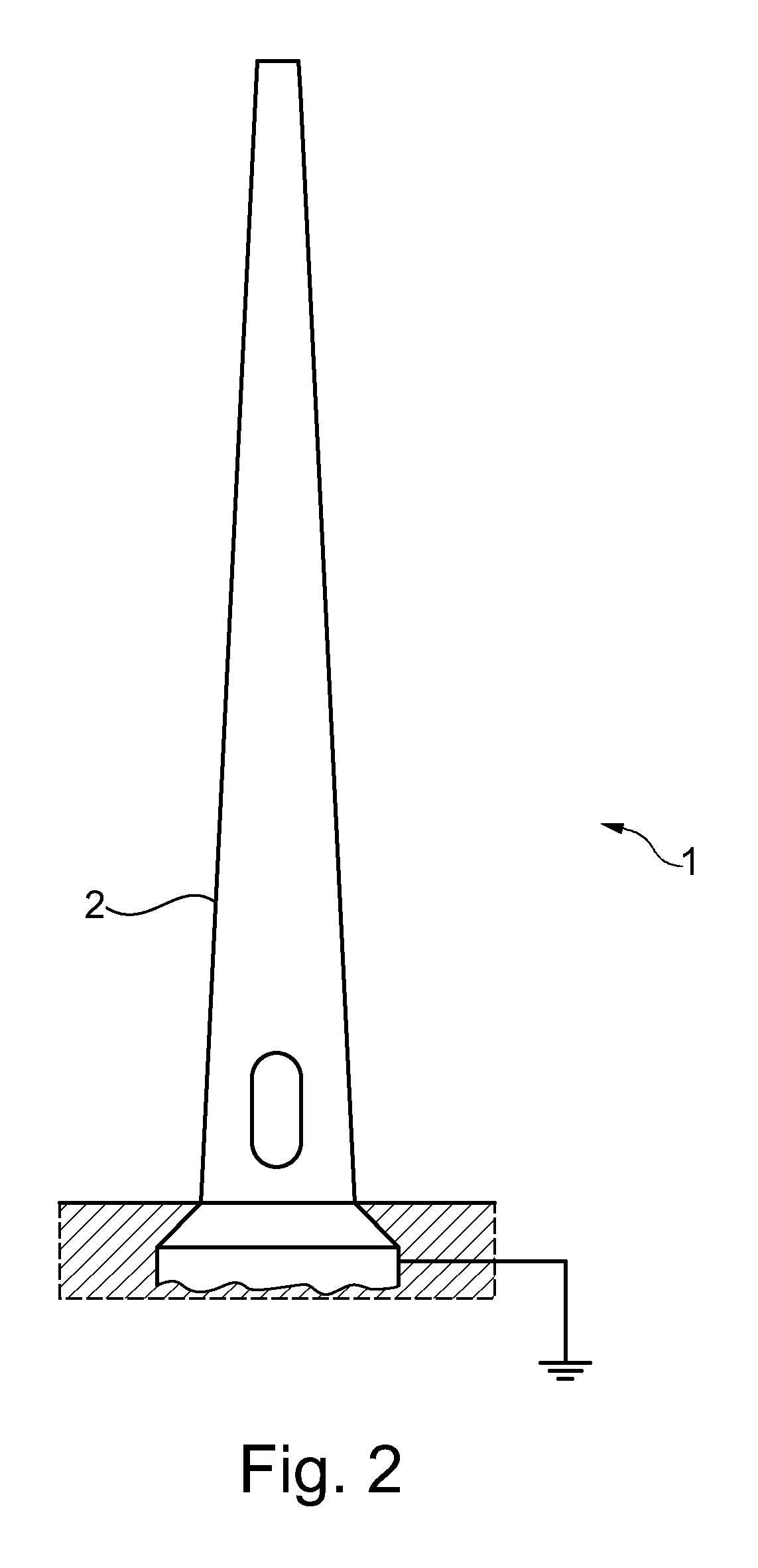
  • Wind turbine tower having a damper

Examples


example

[0046]A tower having a tower damper according to FIG. 10 for a MW wind turbine for wind class IEC IIIa with a hub height of 119 meters including five sections, three cylindrical lower sections having a diameter about 3900 mm and wall thickness ranging from 60 mm at the bottom and down to about 24 mm. The two upper sections range from a diameter of 3900 to about 3200 mm and a wall thickness ranging from 23 mm and down to 13 mm, and then at the uppermost part at 20 mm. The total height is about 116 meters.

[0047]The weight of each section is, starting from the bottom and going upwards:[0048]1. Bottom section 70 ton[0049]2. 69 ton[0050]3. 70 ton[0051]4. 57 ton[0052]5. Top section 41 ton

Calculation of damping effect:

Damping mass of ball shaped damper, m=500 kg

Oscillation mass of tower without nacelle, Mt=39500 kg

Stiffness of the equivalent single mass (tower) system, Ct=269000 N / m

Natural frequency of the tower system, fo=½π*ν*(C / Mt)=0.4 Hz

Tower diameter at ¾ height, Dt=3.5 m

Critical wind...


PUM


Abstract

The present invention relates to wind turbine towers and in particular to such towers having a damper for use when erecting the tower and prior to installing a nacelle on the top of the tower. The invention also relates to a method for damping wind turbine towers. One aspect of the invention involves a wind turbine tower (2) with an upper tower structure (24) and a damper (5) comprising, —a liquidless damper housing (7,8) fixed to the upper structure, —a cylindrical interior surface of the damper housing, and —a damper mass having a horizontal extent which is less than a horizontal extent of the cylindrical interior surface of the damper housing, and —at least one shock absorbing structure, where the damper mass is arranged to, when the tower oscillates, essentially stay in a standstill location, whereby a relative movement between the tower and the damper mass may cause an impact with between the tower mass and the shock absorbing structure dependent on the magnitude of the amplitude of the tower oscillation. A main technical progress is that the damper does not need detailed tuning to the towers natural frequency. As long as the damper mass is sufficient, it may be used for damping a range of tower sizes and heights.

Description

FIELD OF THE INVENTION[0001]The present invention relates to wind turbine towers and in particular to such towers having a damper for use when erecting the tower and prior to installing a nacelle on the top of the tower, but which may also be used for otherwise damping the top or other part of the tower. The invention further relates to a method for damping wind turbine towers.BACKGROUND OF THE INVENTION[0002]In particular tall and slender towers, when being erected or after completed erection, have a tendency to oscillate with high amplitude. The high amplitude is believed to be caused by vortexes from the wind passing around the tower. Apparently this is worsened for high towers, which have a higher portion of the tower being exposed to the wind.[0003]A number of various tower dampers have earlier been proposed, but none which may be removed for reuse in a next tower.SUMMARY OF THE INVENTION[0004]One aspect of the invention involves a wind turbine tower with an upper tower structu...

Claims


Application Information

Patent Timeline
Patent Type & Authority Patents(United States)
IPC IPC(8): E04D13/18E04B1/98E04H12/00F16F7/10F03D7/02F03D80/00
CPCF03D7/0296E04B1/985E04H12/00F03D80/88F03D13/20F03D80/00F16F7/10F05B2250/231F05B2260/964Y02E10/726Y02E10/72Y02E10/728E04H9/0215
Inventor OLLGAARD, BORGEJENSEN, SOREN P.
Owner VESTAS WIND SYST AS
Learn More