Portable optical metrology inspection station and method of operation

a technology of optical metrology and inspection station, which is applied in the direction of mechanical measuring arrangement, instruments, and using mechanical means, etc., can solve the problems of reducing poor stability of sensor and part manipulators, and slow and methodical digitalization operation, so as to improve the accuracy and usefulness of scan data, improve the accuracy of dimensional quality inspection, and improve the effect of stability

Inactive Publication Date: 2017-05-30
LEVEL 3 INSPECTION
View PDF17 Cites 31 Cited by
  • Summary
  • Abstract
  • Description
  • Claims
  • Application Information

AI Technical Summary

Benefits of technology

[0013]An integrated automated 3D Optical Scanning and Computer Aided Inspection System for dimensional inspection of precision manufactured parts. The system is based upon a portable frame having lockable caster wheels for portability and retractable support feet for enhanced stability. When and if needed, the support feet can be enhanced with vibration dampening cushions or bearings to isolate the system from the floor carrying the vibration. The frame includes a part placement area with an optical metrology scanner positioned over a multi-axis robotic arm parts presenter positioner with a gripper in the part placement area, the gripper being specific to the part. The robotic arm is constructed and arranged to grip and manipulate parts within a field of view of the optical metrology scanner. The robotic arm provides multi-axis rotate and tilt maneuverability to allow substantially every needed surface of the part to be scanned with no or minimal human intervention. A computer controller mounted in the frame is electrically coupled to the scanner and robotic arm and creates a scan file for batch-processing an analysis, inspection and reporting operation on a part, or series of part scans. Dimensional comparison and analysis software provides geometric conformance / deviation plus extraction of the dimensions indicated in the CAD model and / or blueprint, and any desired inspections are compared in three dimensions. A pass / fail determination, a partial dimensional inspection report, or a complete dimensional inspection report is generated to meet the requirements. This invention is a unique design and a breakthrough in fast, automated, comprehensive, and accurate dimensional quality inspection capabilities.
[0014]In addition to the primary benefits of measurement accuracy and comprehensiveness that Optical Scanning & computer aided inspection provide, additional advantages are: faster inspection; easier disposition; user / operator readiness; manufacturing shop-floor applicability; and other process, application, and operational advantages.

Problems solved by technology

Moving the scanner manually from location to location around the part in order to address all of the part surfaces for visual access and digitizing is a slow and methodical operation.
These systems have been plagued with vibration problems and sensor and / or part movement, severely reducing the accuracy and usefulness of the scan data.
Gauge Repeatability and Reproducibility (Gauge R&R) studies, as well as inspection results, have shown these problems to be systemic and to result from poor stability of the sensor and part manipulators.

Method used


Image

  • Portable optical metrology inspection station and method of operation
  • Portable optical metrology inspection station and method of operation
  • Portable optical metrology inspection station and method of operation

Examples


Embodiment Construction

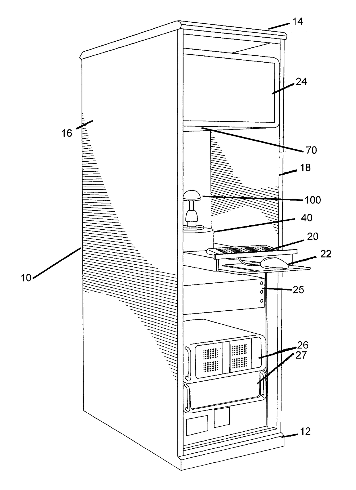
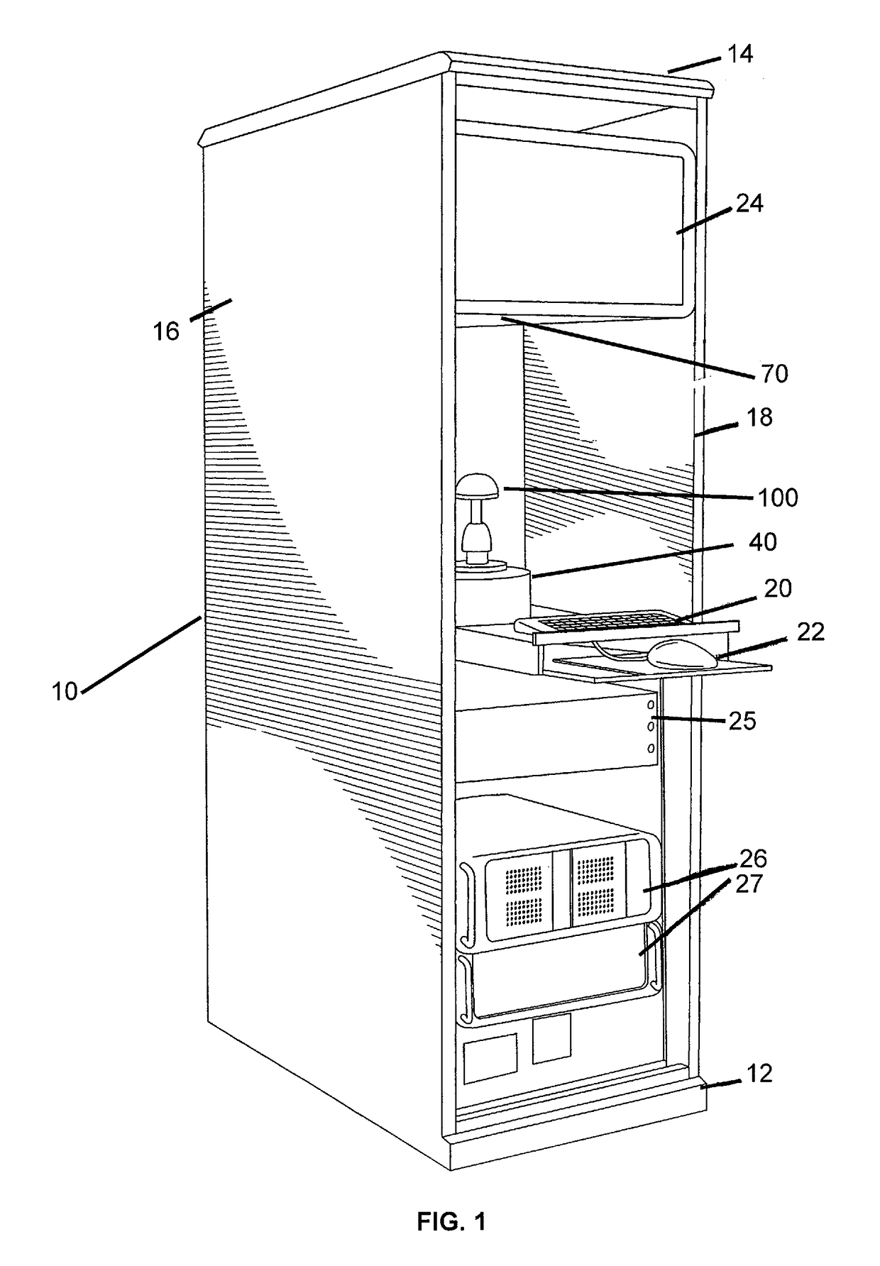
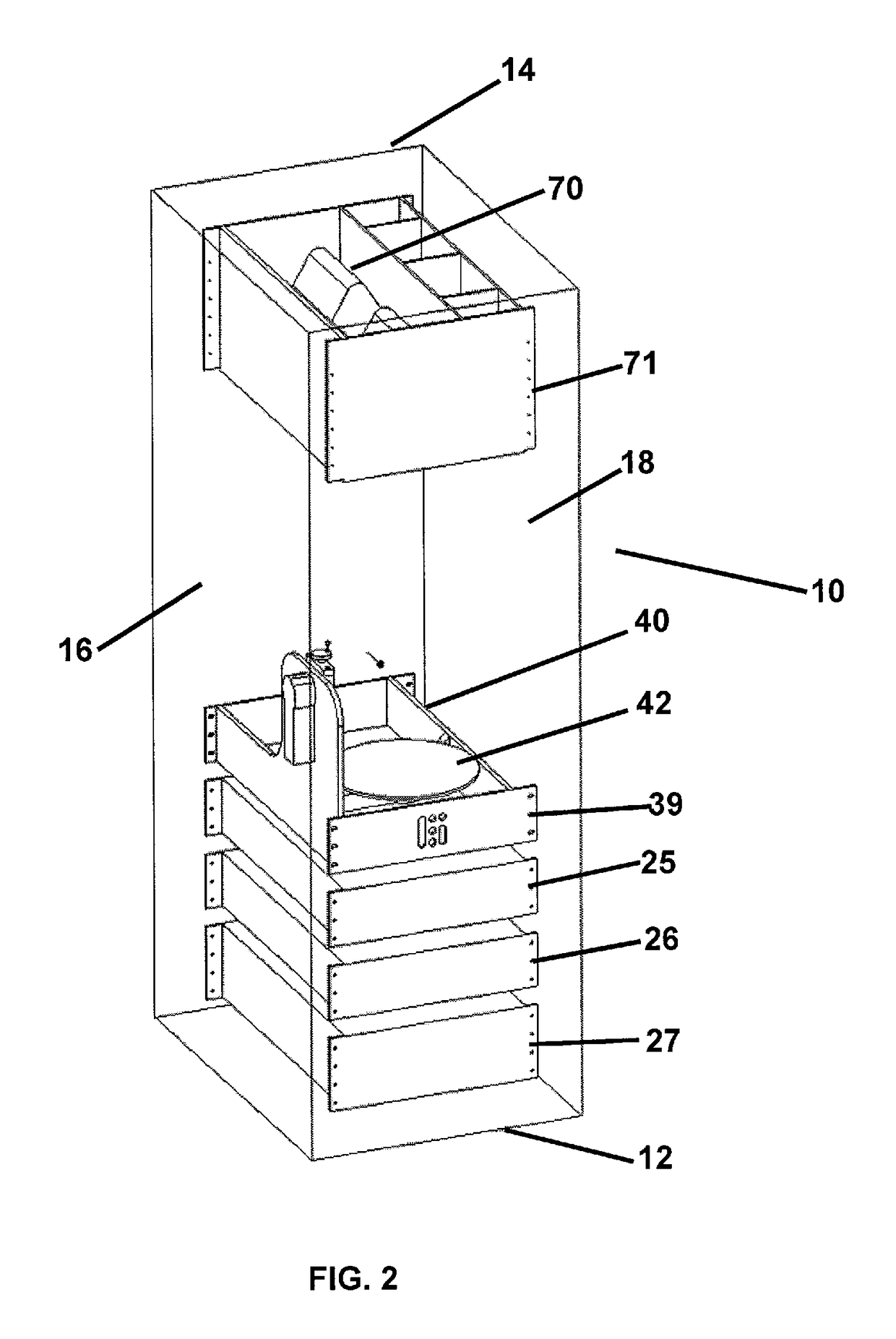
[0024]The invention is an integrated, automated Optical Metrology 3D Scanner, Parts Presenter, and Computer Aided Inspection system that receives a part and rapidly performs all of the process steps required to create the desired inspection outcome determination with varying levels of trendable, traceable, trackable results reporting for part disposition, process optimization, quality control, production stage monitoring, and Statistical Process Control, among other benefits, all with minimal non-technical operator effort beyond inserting the part(s) to be inspected and selecting ‘Start’. This inspection part insertion can also readily be automated to completely eliminate human operators.

[0025]Referring now to FIG. 1, set forth is a pictorial view of the inspection station 10 which is specifically designed to consume a small footprint having a base 12, a top 14, and two side walls 16, 18. The side walls 16 and 18 of the inspection station are constructed and arranged to provide rack...


PUM


Abstract

An integrated automated 3D Optical Scanning and Computer Aided Inspection System for dimensional inspection of precision manufactured parts. The system is based within a portable cabinet having lockable caster wheels for portability and retractably support feet for enhanced stability. The cabinet further includes a part placement area having an optical metrology scanner positioned over a multi-axis robotic arm positioned in the part placement area. The robotic arm is constructed and arranged to grip and manipulate parts within a field of view of the optical metrology scanner. The robotic arm provides multi-axis to rotate and tilt a base to allow substantially every surface of the part to be scanned. Dimensional comparison and analysis software application provide geometric conformance / deviation plus extraction of the dimensions indicated in the part computer aided design (CAD) model.

Description

CROSS REFERENCE TO RELATED APPLICATIONS[0001]This application claims the benefit of priority of U.S. Provisional Patent Application No. 61 / 484,016, filed May 9, 2011, entitled “Portable White Light Scanning Inspection Station and Method of Operation”, the entire contents of which is hereby expressly incorporated by reference.FIELD OF THE INVENTION[0002]The invention is directed to the field of 3D Optical Metrology, including White Light Scanning, and in particular to an integrated, automated 3D Optical Scanning and Computer Aided Inspection System for faster dimensional inspection of precision manufactured parts.BACKGROUND OF THE INVENTION[0003]Manual 3D digitization, commonly known as Optical Scanning, uses equipment and software including full-spectrum optical metrology, limited spectrum (e.g. Light Emitting Diode), and LASER. Typically, a human either places and positions the part in front of the sensor or moves both the part and the sensor to allow surface digitization of the pa...

Claims


Application Information

Patent Timeline
Patent Type & Authority Patents(United States)
IPC IPC(8): G01B21/04G01B11/24
CPCG01B11/24G01B21/047G01B5/0004G01B11/00G01B21/04G01D11/24
Inventor MCAFEE, SCOTT T.GREENE, WILLIAM J.
Owner LEVEL 3 INSPECTION
Why Eureka
Try Eureka