Eureka AIR delivers breakthrough ideas for toughest innovation challenges, trusted by R&D personnel around the world.

Heat-exchanger assembly

Inactive Publication Date: 2017-05-30
OBRIST ENG
View PDF10 Cites 7 Cited by
  • Summary
  • Abstract
  • Description
  • Claims
  • Application Information

AI Technical Summary

Benefits of technology

The invention is a heat exchanger that takes up very little space and is easy to make and assemble. It consists of a flexible pouch made from foil that can be cut and welded to create a strong, sealed vessel for heat exchange. This design allows for high-quality heat transfer at a high pressure and flow rate, making it ideal for use in a variety of applications.

Problems solved by technology

Furthermore, a heat exchanger of said type takes up a relatively large amount of space in a corresponding arrangement, such that said heat exchanger contributes significantly to the structural size of the arrangement.

Method used


Image

  • Heat-exchanger assembly
  • Heat-exchanger assembly
  • Heat-exchanger assembly

Examples


Embodiment Construction

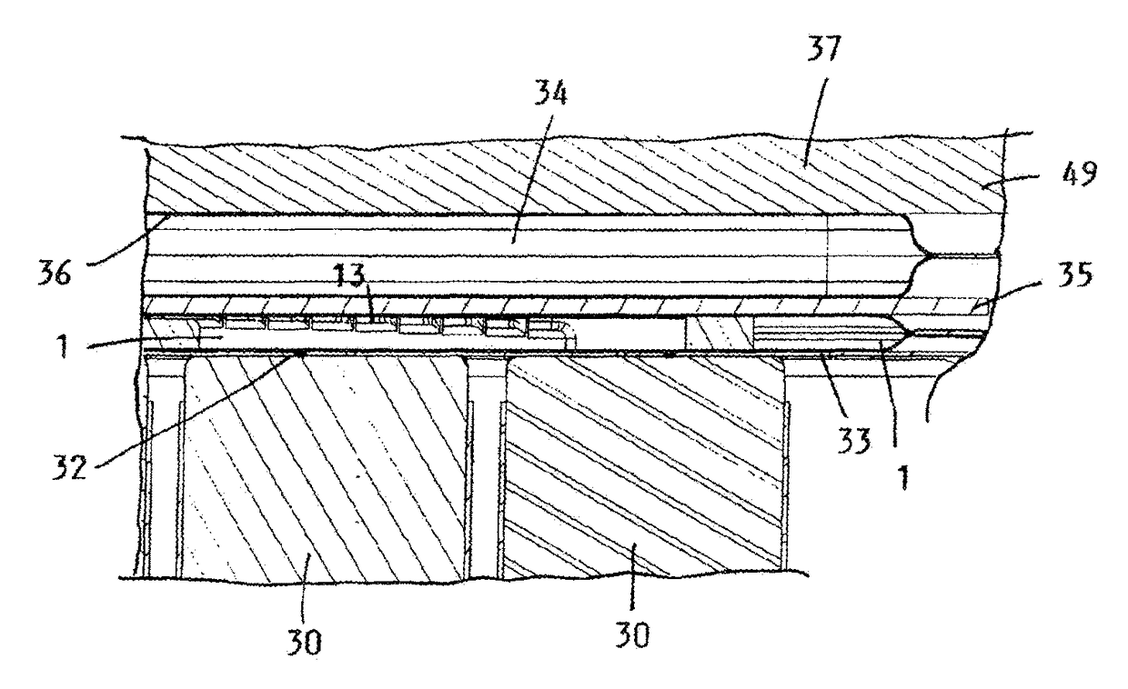
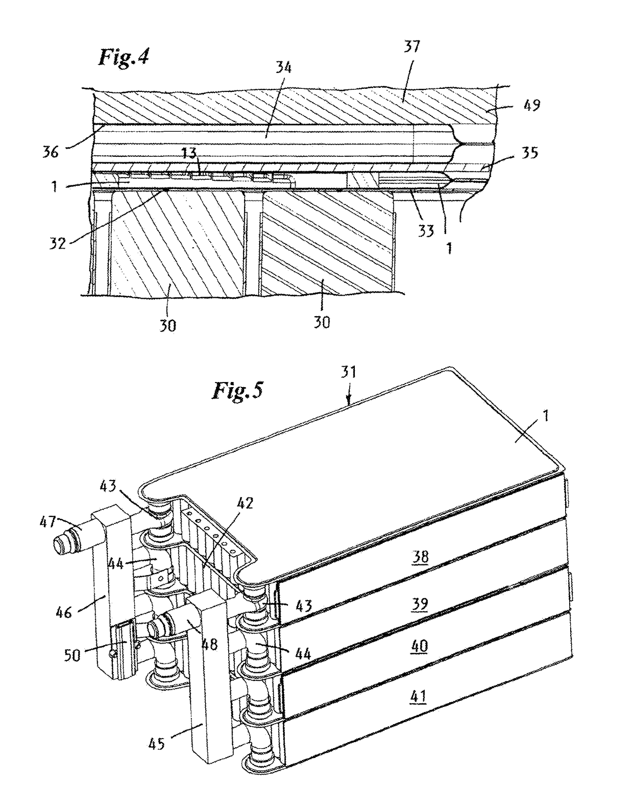
[0025]The heat-exchanging pouch 1 of the heat exchanger arrangement according to the invention illustrated in FIG. 4 is composed of two thin walls 2, 3 which run parallel to one another, which are formed from a foil material and which are sealingly connected to one another in the region of their edges 4.

[0026]A suitable foil material for the production of the heat-exchanging pouch 1, in order to optimize its characteristics with regard to tear resistance, material durability, thermal conductivity, electrical insulation and weldability, is composed of a layered composite of different materials, such as, for example aluminum, polyamide, and polypropylene, and is commercially available with a foil thickness of less than 0.2 mm for various applications. If used for the cooling of a battery, at least one of the outer layers of the foil material should be composed of an electrically insulating plastics material, in order to render the arrangement of an additional electrically insulating f...


PUM


Abstract

For a technical object whose temperature is to be controlled, in particular a battery for an electric vehicle drive, there is provided a heat exchanger arrangement, the heat exchanger of which is in the form of a heat-exchanging pouch which has an inflow and outflow duct and which is in heat-conducting contact with internal surfaces of the object whose temperature is to be controlled. The heat-exchanging pouch is produced in a simple manner by means of edge welding of two foil pieces arranged one above the other. The mounting of said heat-exchanging pouch in a narrow gap space of a heat exchanger arrangement, and good heat transfer to adjacent walls, are made possible by means of a pressure pouch which is likewise formed from a foil material and which is filled with a compressible medium.

Description

CROSS-REFERENCE TO RELATED APPLICATIONS[0001]This application claims priority to European application No. 12196196.5, filed Dec. 7, 2012, which is hereby incorporated by reference in its entirety.BACKGROUND OF THE INVENTION[0002]1. Field of the Invention[0003]The invention relates to a heat exchanger arrangement of a technical object whose temperature is to be controlled, in particular of a battery for an electric vehicle drive, having a flat heat exchanger which has an inflow and outflow duct and which is traversed by a flow of a heat carrier medium, which heat exchanger is in heat-conducting contact with internal surfaces of the object whose temperature is to be controlled.[0004]2. Description of the Related Art[0005]DE102006059989 discloses a heat exchanger arrangement in which a structured cooling plate formed by pressure die casting is in heat-conducting contact with a hose-like cooling pipe and with heat-conducting elements protruding from said cooling pipe, which heat-conduct...

Claims


Application Information

Patent Timeline
IPC IPC(8): H01M10/613H01M10/652H01M10/6557H01M10/643H01M10/617H01M10/6556H01M10/653H01M10/615H01M10/625F28F9/02F28F3/12H01M10/6567
CPCH01M10/6556F28F3/12F28F9/026H01M10/613H01M10/615H01M10/617H01M10/625H01M10/643H01M10/652H01M10/653H01M10/6557F28F2255/02H01M10/6567Y02E60/10H01M10/66
Inventor OBRIST, FRANKGRAZ, MARTINGIESE, PETEROBRIST, OLIVER
Owner OBRIST ENG
Why Eureka
Eureka Blog
Learn More