Systems and methods of thermal transfer and/or storage

a technology of thermal energy storage and system, applied in the field of heat exchange and/or thermal energy storage methods and apparatuses, can solve the problems of inability to build power plants at any location, inability to meet the needs of small-scale emergency power supply, and high cost nature to achieve the effect of significantly difficult mechanical system design

Active Publication Date: 2017-06-06
BLUELAGOON TECH
View PDF26 Cites 13 Cited by
  • Summary
  • Abstract
  • Description
  • Claims
  • Application Information

AI Technical Summary

Problems solved by technology

For example, nuclear and coal-fired power plant need to shift their generated power during low demand hours to peak demand hours of the grid; wind power and solar power plants due to their intrinsically intermittent nature, need even more energy storage solution since their energy resources are more uncontrollable to meet the grid demand, which may introduce instability for the grid.
Although there are continued efforts to improve battery technologies, their intrinsic high cost nature limits their applications to small scale emergency power supplies.
However, these two solutions all require special geologic conditions, i.e. geologic conditions to build two low and high attitude water reservoirs or natural underground air-tight high pressure air-reservoir, which are rarely available in local power plants.
As a result, power plants cannot be built at any location even if other environmental effects are not considered.
In these processes, water cooling operation cost also composed of large percentage of the total operating cost.
In the past, air-cooling methods have been tried, however, not very successfully due to expensive equipment and the high electricity consumption involved.
However, the unstable nature of solar radiation, caused either by clouds or sunset, requires a thermal storage sub-system in CSP plants in order to qualify them as a base load power supplier.
This requirement normally causes higher system maintenance costs.
For gas type HTF, steam can be used; however, its pressure and cost will be too high for high temperature steam applications; hot air can be used as gas type HTF; however, it has very low heat capacity and needs high electricity consumption to create high flow rate.
There are several problems with this approach: a) it requires several high temperature specialty pumps that can handle high temperature and very corrosive molten salt between the two containers, conducting oil-molten salt heat exchanger and molten salt-steam generation heat exchanger; b) it requires specialty heat exchanger due to the natures of molten salt; c) the construction cost is still quite high: for example, for large scale deployment, the thermal storage device construction cost can be $40 / kWh of heat.
For a distributed solar collecting field, this will significantly increase the complexity and the cost for the transport pipe, both in their construction and in their maintenance and services.
However, it can only be used in indirect thermal energy storage approach.
However, a disadvantage of solid state sensible storage method is that the heat exchange and working temperature decrease during discharge, since sensible heat thermal storage materials' temperature decreases as thermal energy decreases.
Another problem is that the thermal conductivity and heat transfer coefficients are low.
This will dramatically increase the cost for such steam transport pipes as well as the thermal storage container cost.
On the other hand, to reduce the cost, the pressure of the directly generated steam has to be lowered, which will decrease the working efficiency for steam turbine.
This thermal storage approach can only be used to smooth the solar radiation intensity fluctuations during the day, which can provide 1 hour of steam to the turbine generator.
However, due to high cost of pressurized vessels, this approach is very hard to be deployed in large scale.
However, liquid-gas phase change latent heat storage is difficult to use due to extremely large volume change at the phase change.
Therefore, it is not economical to utilize latent heat for thermal energy storage with liquid-gas phase transition, because a large container with very high pressure inside the storage container is required to accommodate the gas phase volume, resulting significantly reduced thermal energy storage density and difficult mechanical structure design for the thermal storage apparatus.
Although there are many studies on PCM thermal storage, there are still major difficulties of using solid-liquid phase change materials (PCM) as latent heat storage.
The volume change makes mechanical system design considerably difficult.
The second is difficult to maintain good heat conduction between solid-liquid PCMs and HTF.
Heat transfer between the storage medium, HTS and working medium has not been solved properly, as a result, no commercial application of latent heat storage method and apparatus have succeeded so far.

Method used


Image

  • Systems and methods of thermal transfer and/or storage
  • Systems and methods of thermal transfer and/or storage
  • Systems and methods of thermal transfer and/or storage

Examples


Embodiment Construction

[0047]Reference will now be made in detail to the invention, examples of which are illustrated in the accompanying drawings. The implementations set forth in the following description do not represent all implementations consistent with the claimed invention. Instead, they are merely some examples consistent with certain aspects related to the invention. Wherever possible, the same reference numbers will be used throughout the drawings to refer to the same or like parts.

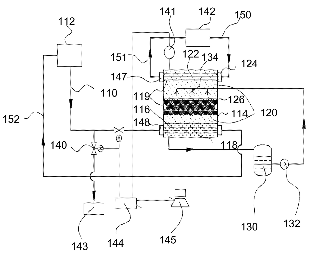
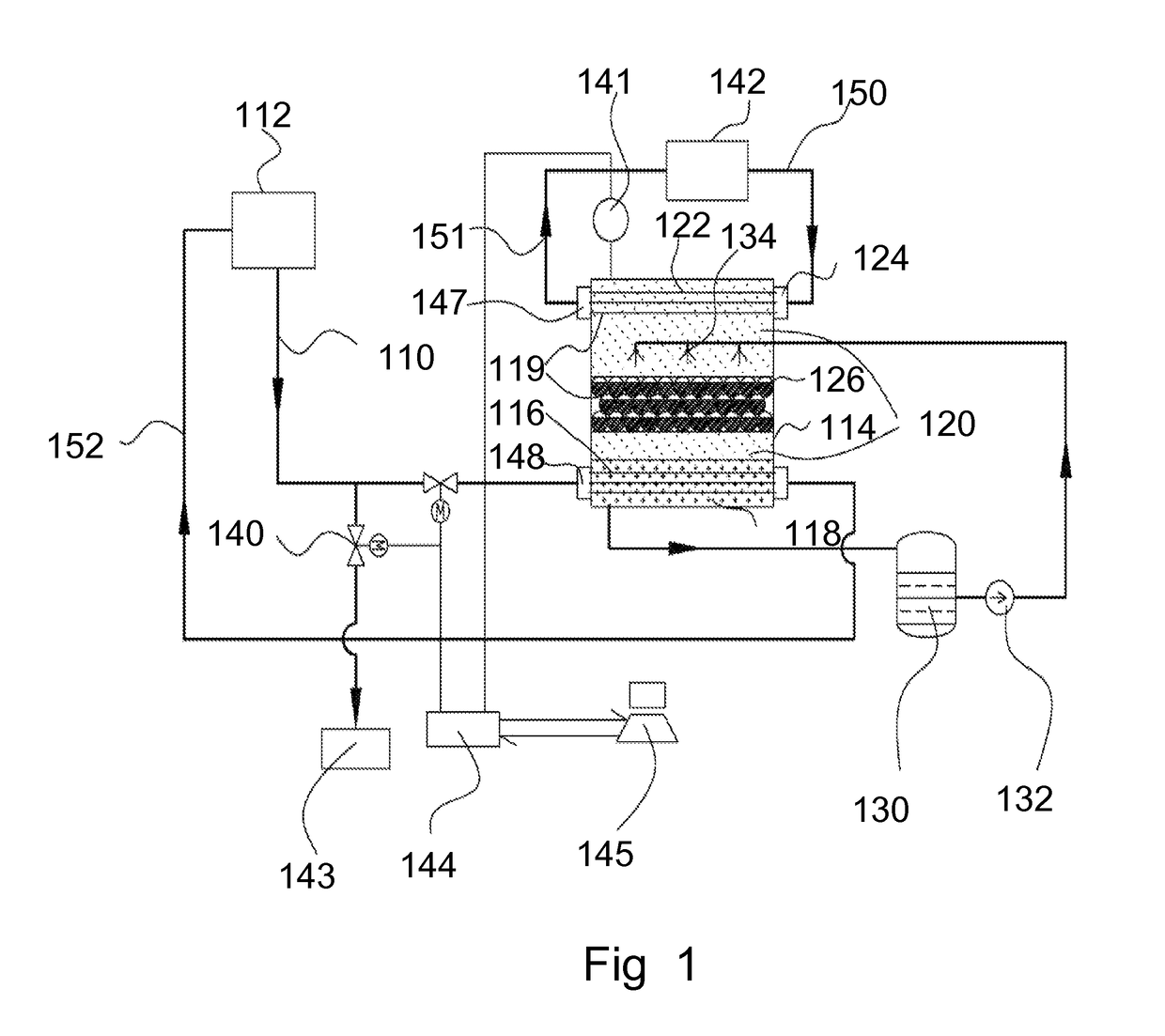
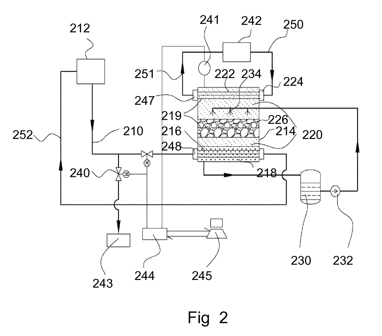
[0048]Aspects of the innovations, such as those set forth in some of the implementations below, may relate to systems and methods of integrating an evaporation-condensation heat exchange mechanism with a phase change latent heat energy storage apparatus, using liquid-gas phase change materials as heat exchange media and solid-liquid phase change materials as thermal energy storage media. However, it should be understood that the inventions herein are not limited to any such specific illustrations, but are defined by ...


PUM

PropertyMeasurementUnit
melting pointaaaaaaaaaa
temperatureaaaaaaaaaa

Abstract

Systems, methods, and computer-implemented embodiments consistent with the inventions herein are directed to storing and / or transferring heat. In one exemplary implementation, there is provided a system for transferring / storing heat comprised of a heat exchange / storage apparatus including a chamber, and a heat input device adapted to heat / provide a vapor into the chamber. Other exemplary implementations may include one or more features consistent with a heat output device through which a working medium / fluid passes, a thermal storage medium located within the chamber, and / or a heat exchange system that delivers a heat exchange medium / fluid to the thermal storage medium.

Description

[0001]This application is a continuation-in part of U.S. application Ser. No. 12 / 885,411, filed Sep. 17, 2010, which claims priority to and benefit of U.S. provisional application No. 61 / 276,885, filed Sep. 17, 2009, all of which are incorporated herein by reference in their entirety for all purposes.FIELD[0002]Aspects of the innovations herein relate to heat exchange and / or thermal energy storage methods and apparatus. More specifically, exemplary innovations relate to the application of phase change materials (PCMs) as thermal energy storage materials and / or heat exchange media.BACKGROUND INFORMATION[0003]Energy storage is important in many energy consumption applications, including conventional and renewable utility power generation, building air-conditioning and heating, and industry process heating. For example, nuclear and coal-fired power plant need to shift their generated power during low demand hours to peak demand hours of the grid; wind power and solar power plants due t...

Claims


Application Information

Patent Timeline
Patent Type & Authority Patents(United States)
IPC IPC(8): F25D11/00F28D13/00F28D15/00F25D17/02F28D17/00F28D20/02F28D15/02C09K5/06C09K5/10F24H7/02F28C3/00F28D20/00F24J2/32F28F25/06F24S10/95
CPCF28D15/02C09K5/063C09K5/10F24H7/02F28C3/005F28D20/0056F28D20/028F24D2220/10F24J2/32F28D2020/006F28D2020/0021F28D2020/0047F28F25/06F28F2265/14Y02E60/142Y02E60/145F24S10/95Y02E60/14
Inventor XIANG, XIAODONG
Owner BLUELAGOON TECH
Why Eureka
Try Eureka