Lock miter set-up jig

a technology for setting up jigs and miter cutters, which is applied in the direction of measuring/indication equipment, metal-working apparatus, gauging means, etc., can solve the problems of inability to accurately set up the lock miter cutter, insufficient conventional devices and methods for making both settings, and inability to meet the needs of the user, so as to facilitate the making of corners, facilitate the setting, and advance the art of woodworking

Active Publication Date: 2017-06-20
INFINITY CUTTING TOOLS INC
View PDF3 Cites 2 Cited by
  • Summary
  • Abstract
  • Description
  • Claims
  • Application Information

AI Technical Summary

Benefits of technology

[0038]The primary object of the invention is to advance the art of wood working by providing a jig that facilitates the making of corners.
[0039]A closely related object is to provide a jig that facilitates the set-up of a conventional lock miter router bit and fence for boards of common thicknesses as well as boards of differing thicknesses.

Problems solved by technology

Conventional devices and methods for making both settings are often extremely inadequate, incorrect, or so imprecise that all too often the procedure becomes one of trial and error.
The number and capabilities of prior art devices that can be used for accurate lock miter cutter setups are extremely limited.
These blocks are machined with a lock miter cutter after it has been properly set up, often by trial and error.
The disadvantages of these blocks are that they can only be used with the specific style and size of lock miter cutter used to create them and only with boards that are exactly the same thickness as the set-up block, usually ¾″.
Such assumptions are seldom accurate.
No prior art device harnesses the power of this geometric fact and therefore the known devices are of limited use in making precise setups to cut standard lock miters and are of no use in making non-standard and offset lock miter setups.

Method used


Image

  • Lock miter set-up jig
  • Lock miter set-up jig
  • Lock miter set-up jig

Examples


Embodiment Construction

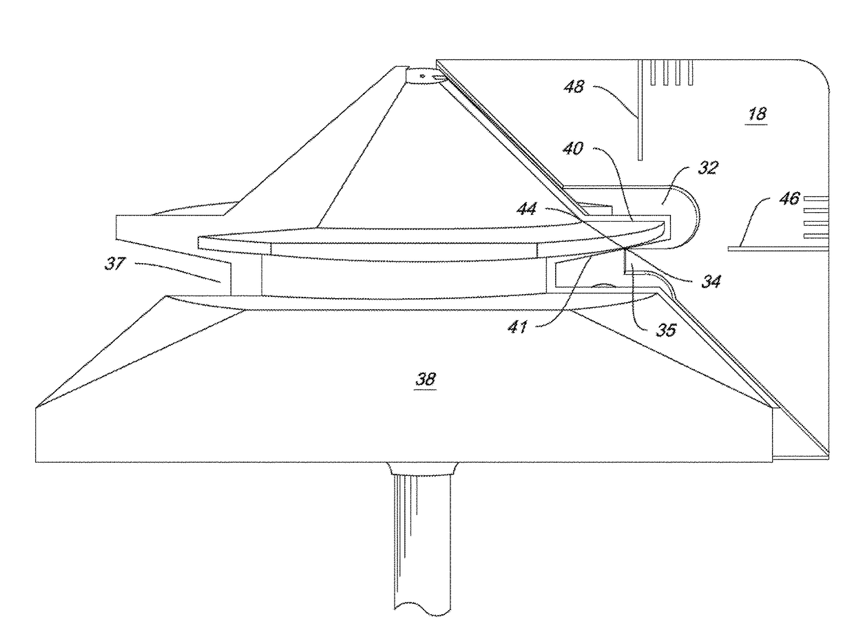
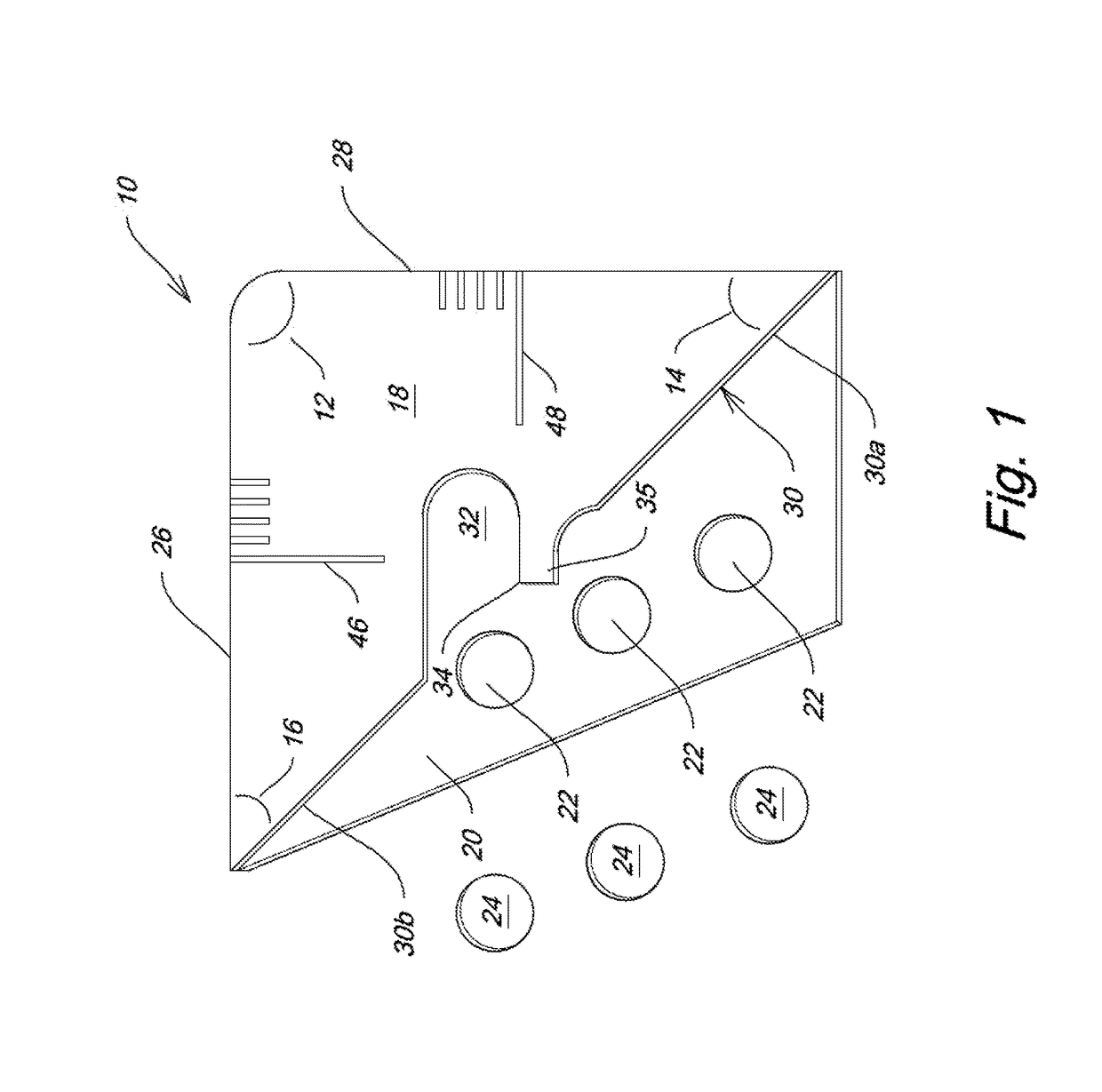
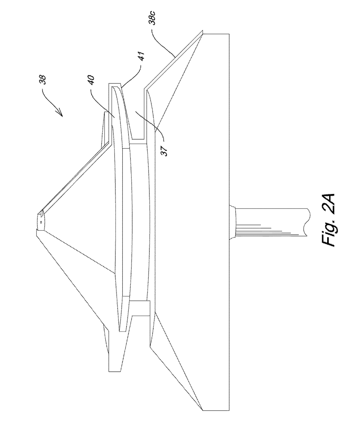
[0056]FIG. 1 depicts an illustrative embodiment of the novel structure which is denoted as a whole by the reference numeral 10.

[0057]Novel jig 10 can be made of any size and of any durable material. Angle 12 is a ninety degree angle, angle 14 is a forty five degree (45°) angle, and angle 16 is therefore a forty five degree (45°) angle as well.

[0058]Jig 10 has a flat elevated surface 18 and a recessed flat surface 20. Flat elevated surface 18 is preferably about 3 / 16th of an inch in thickness and recessed flat surface 20 is about half that.

[0059]A plurality of pockets, collectively denoted 22, are milled in recessed flat surface 20 and each pocket receives a rare earth magnet 24 therewithin. The magnets are preferably press fit within their respective pockets but any suitable connection means is within the scope of this invention.

[0060]First side 26 in this preferred embodiment is 1¼″ in length and second side 28 has the same length. Third side 30 therefore would be 1.7678 inches (th...


PUM


Abstract

A woodworking jig is used to set cutter height and horizontal fence position when forming lock miter joints with a forty-five degree (45°) lock miter cutter on a router table or shaper. Vertical and horizontal reference lines are formed on the exterior surface of the jig. Setup is accomplished by adjusting the cutter height and fence position until the appropriate reference lines on the jig align with centerlines or centerline-derived lines on the edge of the stock. Using the appropriate reference lines, the jig is used to complete setups for standard lock miter joints with boards of equal thickness, non-standard lock miters joints with boards of different thicknesses, and offset lock miter joints. The jig has no moving parts, requires no calibration or measuring devices, and works with any lock miter router bit and most shaper cutters. The jig locates the geometric center of the router bit profile with precision.

Description

BACKGROUND OF THE INVENTION[0001]1. Field of the Invention[0002]This invention relates, generally, to the art of wood working. More particularly, it relates to tools for forming corners made of boards that share a common thickness, that have differing thicknesses, or where an offset of the joint line is desired.[0003]2. Description of the Prior Art[0004]A forty five degree (45°) lock miter router bit or shaper cutter, hereinafter also referred to sometimes as the cutter, is used to make forty five degree (45°) beveled cuts in the edges or ends of two boards that when assembled create a ninety degree (90°) joint. Contours in the cutter also create mating male and female profiles in a portion of the adjoining edges. These profiles increase gluing surfaces which results in a joint that is stronger than a straight miter. They also prevent the assembled joint from slipping along the joint line when clamped. The cutter geometry and the procedure of cutting one board in the horizontal posi...

Claims


Application Information

Patent Timeline
Patent Type & Authority Patents(United States)
IPC IPC(8): B27G23/00B23Q17/22
CPCB27G23/00B23Q17/2233
Inventor SCHAFFTER, ALAN B.
Owner INFINITY CUTTING TOOLS INC
Why Eureka
Try Eureka