Energy management device for a vehicle having a plurality of different energy sources

a technology of energy management device and vehicle, which is applied in the direction of navigation instruments, instruments, transportation and packaging, etc., can solve the problems of limited electricity generation using kinetic energy of the vehicle, motor drive using electrical energy, and electrical power regeneration by a regenerative technology, and achieve good energy efficiency

Active Publication Date: 2017-07-11
MITSUBISHI ELECTRIC CORP
View PDF42 Cites 10 Cited by
  • Summary
  • Abstract
  • Description
  • Claims
  • Application Information

AI Technical Summary

Benefits of technology

[0011]It is an object of the present invention to provide a vehicle energy management device capable of controlling vehicle devices with good energy efficiency.
[0012]An energy management device according to the present invention is used in a vehicle including a plurality of vehicle devices driven by different energy sources. The vehicle energy management device includes a travel route calculator, an energy consumption-related information obtaining unit, an energy consumption amount computing unit, a control plan preparing unit, a vehicle device control unit, and a feedback control unit, as described below. The travel route calculator calculates a travel route of the vehicle. The energy consumption-related information obtaining unit obtains energy consumption-related information which is information related to energy consumption of the vehicle along the travel route. The energy consumption amount computing unit calculates, based on the energy consumption-related information, an estimated value of an energy consumption amount by the plurality of vehicle devices when the vehicle travels along the travel route. The control plan preparing unit prepares a control plan for the plurality of vehicle devices based on the estimated value of the energy consumption amount by the plurality of vehicle devices. The vehicle device control unit controls the plurality of vehicle devices according to the control plan. The feedback control unit performs feedback control of the plurality of vehicle devices so as to reduce a difference between the estimated value and an actual measured value of the energy consumption amount by the plurality of vehicle devices.
[0013]The energy management device according to the present invention obtains in advance energy consumption-related information along a travel route, and calculates, based on the information, an estimated value of the energy consumption amount by a plurality of vehicle devices when the vehicle travels along the travel route. This allows both a change in the remaining amount of the fuel and a change in the charge level of the storage battery over the entire travel route to be grasped in advance, and thus control of vehicle devices which has conventionally been impossible can be performed.
[0014]For example, in a vehicle using both the engine and the motor as the power source, a control plan for vehicle devices can be prepared so that motor drive using electrical energy and electrical power regeneration by a regenerative brake during deceleration are not limited by the charge status of the storage battery. This can prevent a decrease in fuel mileage due to driving the engine more than necessary, and prevent kinetic energy from being wasted by a friction brake as heat.

Problems solved by technology

A hybrid vehicle has a drawback in that motor drive using electrical energy, and electrical power regeneration by a regenerative brake during deceleration (electricity generation using kinetic energy of the vehicle), may be limited by the charge status of the storage battery on the vehicle.
Conversely, when the charge level of the storage battery is near an upper limit, regenerated electrical power cannot be charged to the storage battery, and therefore the regenerative brake cannot be used even if regeneration can be performed on a downgrade.
This necessitates use of a friction brake, which will waste kinetic energy as heat.
However, with the conventional method in which the operation mode is selected based on current sensor information, the timing to start electricity generation using engine output power cannot be determined.
Thus, the operation mode switching control as described above cannot be performed.

Method used


Image

  • Energy management device for a vehicle having a plurality of different energy sources
  • Energy management device for a vehicle having a plurality of different energy sources
  • Energy management device for a vehicle having a plurality of different energy sources

Examples


Embodiment Construction

[0021]

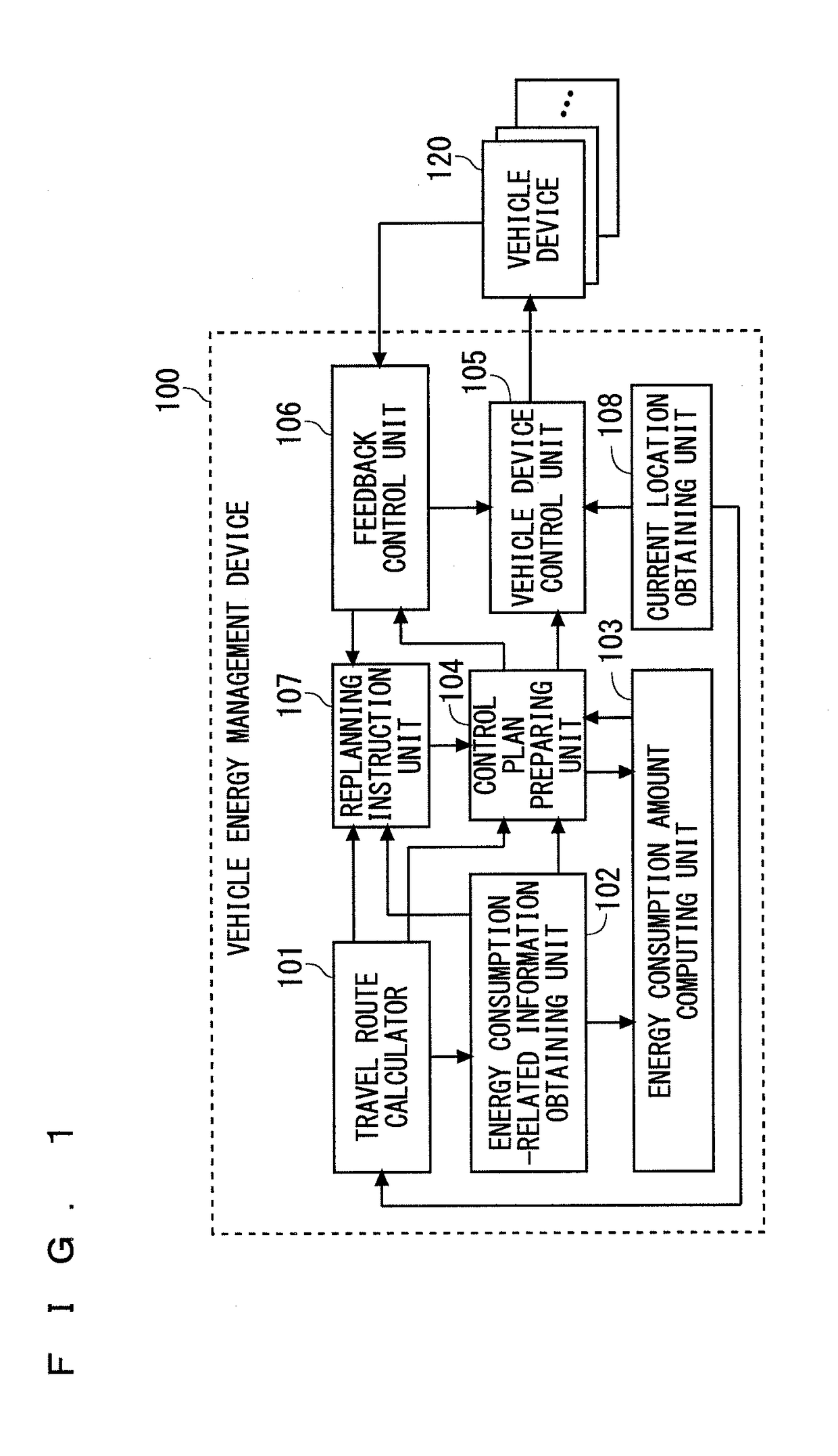
[0022]FIG. 1 is a block diagram showing a configuration of a vehicle energy management device according to a first preferred embodiment. The vehicle energy management device according to the present invention can be widely applied to vehicles having two or more energy sources. However, this preferred embodiment is described in terms of a vehicle energy management device installed in a vehicle that utilizes two types of energy, i.e., fuel energy and electrical energy, as the power source.

[0023]A vehicle energy management device 100 controls vehicle devices 120, such as a motor, an engine, a generator, and the like, of a vehicle (hereinafter also referred to as “own vehicle”) mounted with the vehicle energy management device 100. Note that, when the vehicle reduces its speed, a motor can act as a generator (regenerative brake) that regenerates electrical power. The vehicle devices 120, which are controlled by the vehicle energy management device 100, may include an air condition...


PUM


Abstract

In a vehicle energy management device, a travel route calculator calculates a travel route of a vehicle, and an energy consumption-related information obtaining unit obtains energy consumption-related information along the travel route. An energy consumption amount computing unit calculates, based on the energy consumption-related information, an estimated value of an energy consumption amount by vehicle devices (required travel energy amount) when the vehicle travels along the travel route. A control plan preparing unit prepares a control plan for the vehicle devices based on the required travel energy amount. A feedback control unit performs feedback control of the vehicle devices to reduce a difference between the estimated value and an actual measured value of the energy consumption amount by the vehicle devices.

Description

BACKGROUND OF THE INVENTION[0001]Field of the Invention[0002]The present invention relates to a vehicle energy management device for managing energy consumption of a vehicle, and more particularly, to a vehicle energy management device suitable for a vehicle having a plurality of different energy sources.[0003]Description of the Background Art[0004]A vehicle that utilizes a plurality of different energy sources such as fuel energy and electrical energy, i.e., a so-called hybrid vehicle, has various operation modes in order to reduce an energy consumption amount. Examples of operation modes of a hybrid vehicle include, for example, a mode in which only power output from the engine is used as the power source to travel, a mode in which only power output from the motor is used as the power source to travel, a mode in which power output from both the engine and the motor is used as the power source to travel, and a mode in which engine output power is used to generate electricity, which...

Claims


Application Information

Patent Timeline
Patent Type & Authority Patents(United States)
IPC IPC(8): B60W10/06G01C21/34B60W10/08B60W50/00B60W20/00B60W20/40B60W20/12B60L50/16
CPCB60W20/12B60W10/06B60W10/08B60W20/40G01C21/3469B60W2050/0088B60W2550/12B60W2550/142B60W2550/146B60W2550/402B60W2720/103Y02T10/6286B60W10/04B60W10/30B60W50/04B60W2552/30B60W2552/20B60W2552/15B60W2555/20B60W2556/50Y02T10/62
Inventor MATSUNAGA, TAKANORIFUJIOKA, HIROSHISUGIYAMA, AKINOBUMORI, KOHEISHIROZONO, MASATAKANAKAMURA, NOBUTAKA
Owner MITSUBISHI ELECTRIC CORP
Why Eureka
Try Eureka