Supercharge Your Innovation With Domain-Expert AI Agents!

Quasi TEM dielectric travelling wave scanning array

a scanning array and dielectric technology, applied in the field of coupling, can solve problems such as bandwidth constraints, and achieve the effect of increasing the instantaneous bandwidth of the array

Active Publication Date: 2017-07-11
ANTENUM INC
View PDF18 Cites 2 Cited by
  • Summary
  • Abstract
  • Description
  • Claims
  • Application Information

AI Technical Summary

Benefits of technology

This patent discusses a way to control the beamwidth and direction of a series fed antenna array by adjusting the size of gaps between layers on a substrate. The gaps can be controlled using a piezoelectric actuator or a mechanical position control, which can influence the beamwidth and direction of the array. Each tap in the array can act as a separate radiating element, and delay elements can be added to increase the array's bandwidth. Overall, this patent offers a way to create efficient and precise antenna arrays.

Problems solved by technology

However, series fed arrays are typically frequency sensitive therefore leading to bandwidth constraints.

Method used


Image

  • Quasi TEM dielectric travelling wave scanning array
  • Quasi TEM dielectric travelling wave scanning array
  • Quasi TEM dielectric travelling wave scanning array

Examples


Embodiment Construction

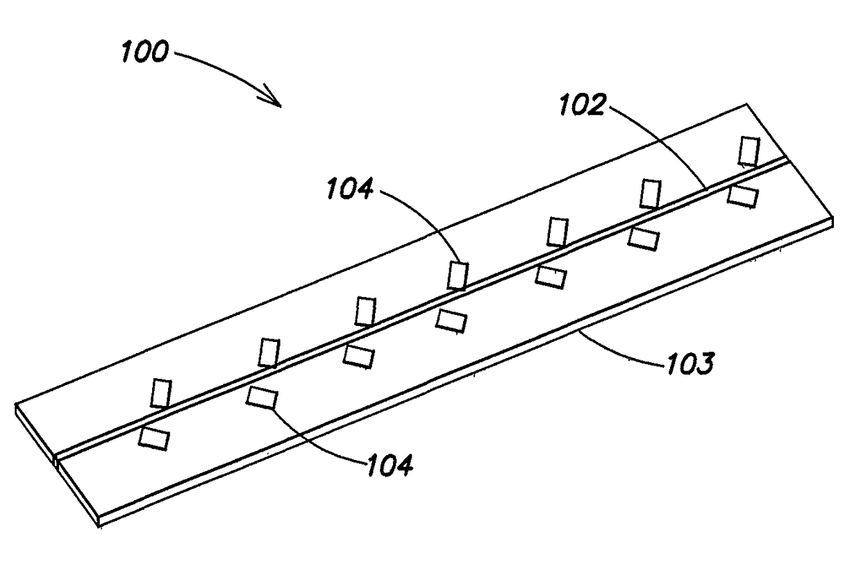
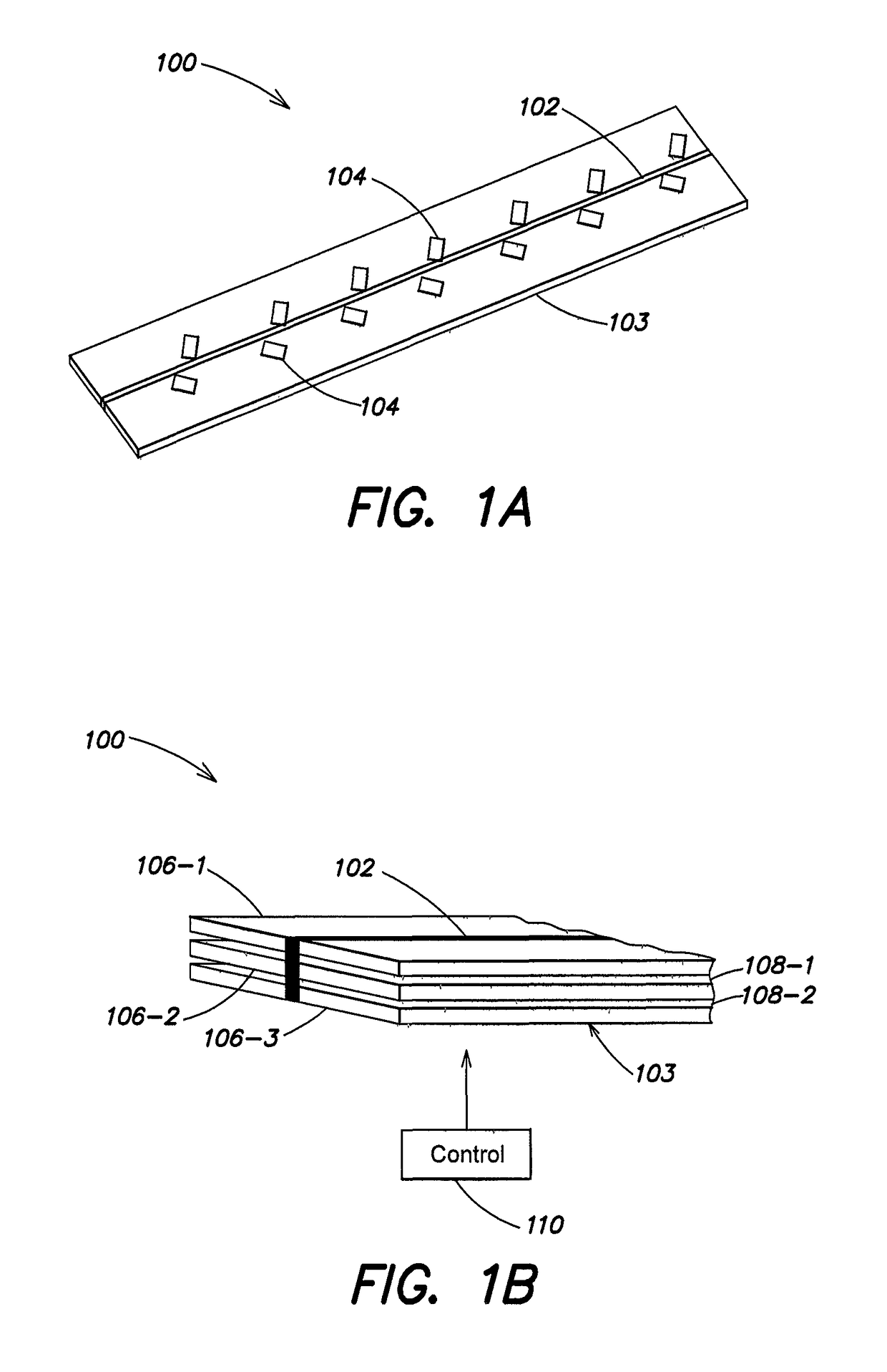
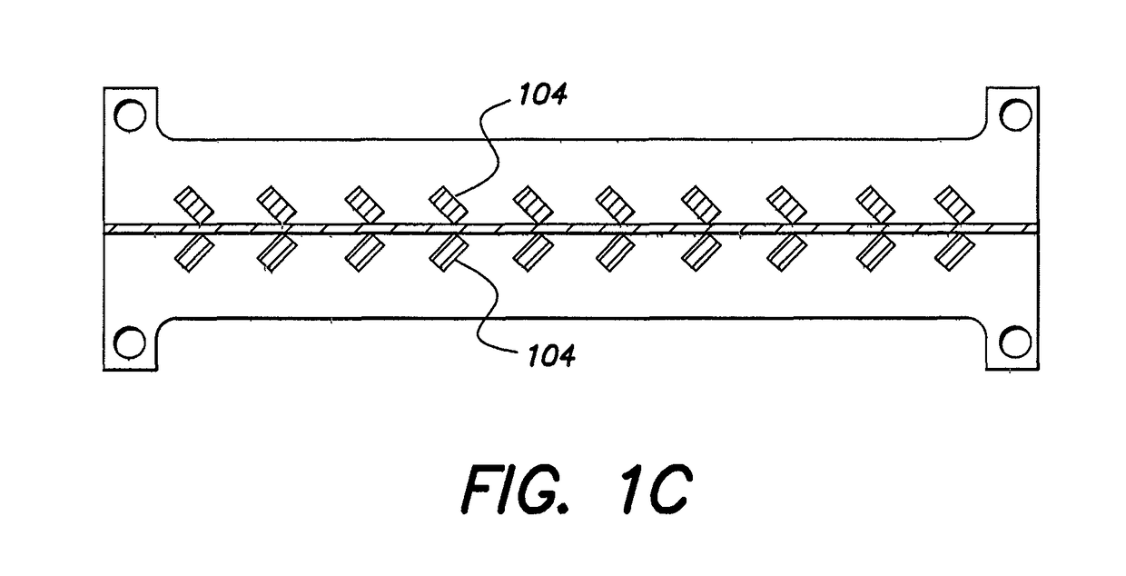
[0027]Antenna array elements are fed in series by a coupling feed structure formed from a Transverse Electromagnetic Mode (TEM) or quasi-TEM transmission line disposed adjacent an adjustable substrate. The adjustable substrate may be formed of two or more dielectric layers, with the dielectric layers having a reconfigurable gap between them. The transmission line may be a low dispersing microstrip, stripline, slotline, coplanar waveguide, or any other quasi-TEM or TEM transmission line structure. The gaps introduced in between the dielectric layers provide variable properties, such as a variable dielectric constant (variable epsilon structure) to control the scanning of the array. Alternatively, a piezoelectric or ElectroActive Polymer (EAP) actuator material may provide or control the gaps between layers, allowing these layers to expand, or causing a gel, air, gas, or other material to compress. Any other arrangement may be used to enable the dielectric constant of the adjacent str...


PUM


Abstract

A dielectric travelling wave antenna (DTWA) using a TEM mode transmission line and variable dielectric substrate.

Description

CROSS REFERENCE TO RELATED APPLICATIONS[0001]The present application claims the benefit of U.S. Provisional Patent Application Ser. No. 61 / 987,781, entitled “Quasi Tem Dielectric Travelling Wave Scanning Array” which was filed on May 2, 2014 the entire contents of which is hereby incorporated by reference.BACKGROUND[0002]Technical Field[0003]This patent relates to series-fed phased array antennas and in particular to a coupler that includes a transmission line structure disposed over an adjustable dielectric substrate.[0004]Background Art[0005]Phased array antennas have many applications in radio broadcast, military, space, radar, sonar, weather satellite, optical and other communication systems. A phased array is an array of radiating elements where the relative phases of respective signals feeding the elements may be varied. As a result, the radiation pattern of the array can be reinforced in a desired direction and suppressed in undesired directions. The relative amplitudes of th...

Claims


Application Information

Patent Timeline
Patent Type & Authority Patents(United States)
IPC IPC(8): H01Q3/34H01Q21/24H01Q3/44H01Q13/20H01Q21/00H01Q21/06H01P5/19H01P5/18
CPCH01Q13/206H01Q3/34H01Q3/443H01Q21/24H01P5/185H01P5/19H01Q21/0037H01Q21/0075H01Q21/065
Inventor APOSTOLOS, JOHN T.MOUYOS, WILLIAMMCMAHON, BENJAMINMOLEN, BRIANGILI, PAUL
Owner ANTENUM INC
Features
  • R&D
  • Intellectual Property
  • Life Sciences
  • Materials
  • Tech Scout
  • Unparalleled Data Quality
  • Higher Quality Content
  • 60% Fewer Hallucinations
Learn More